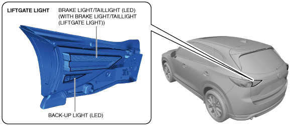
LIFTGATE LIGHT


id091800011900


Purpose

•  The liftgate lights are used to signal the following conditions to vehicles/people at the rear.
―  Back-up light: Signals that the vehicle is backing up.
―  Brake light: Signals a vehicle deceleration or stop. (with brake light/taillight (liftgate light))
―  Taillight: Signals the presence of the vehicle to vehicles/people at the rear during nighttime. (with brake light/taillight (liftgate light))

Function

•  The related light turns on according to the operation of each part.

Operation part

Related light

•  TCM (selector lever) (ATX)
•  Back-up light switch (shift lever) (MTX)
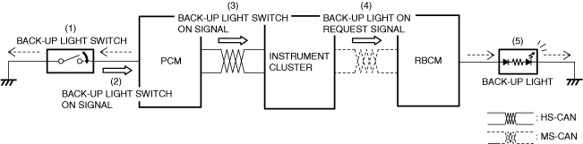
Back-up light
Brake switch (with brake light/taillight (liftgate light))
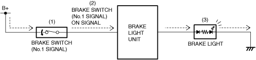
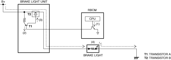
Brake light
Light switch (TNS (parking lights)) (with brake light/taillight (liftgate light))
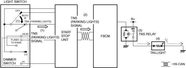
Taillight


Structure/Construction

•  The liftgate light is integrated with the following parts.
―  Back-up light (LED)
―  Brake light/taillight (LED) (with brake light/taillight (liftgate light))
Note
•  Fogging or condensation may occur inside the liftgate lights, however, it is a natural phenomenon occurring as a result of a temperature difference between the interior and exterior of the liftgate lights and it does not affect the light performance.
•  Fogging or condensation occurring as a natural phenomenon will dissipate when the temperature inside the liftgate light rises after the back-up light is turned on and a period of time has elapsed.
ac5wzn00004703

Operation


Back-up light

ATX
1.  When the selector lever is in the R position with the ignition switched ON (engine off or on), the TCM sends (1) an R position signal to the instrument cluster via CAN communication.
2.  When the instrument cluster receives the R position signal, it sends (2) a back-up light on request signal to the rear body control module (RBCM).
3.  When the rear body control module (RBCM) receives the back-up light on request signal, it turns the back-up light on (3).
ac5uun00002532
MTX
1.  When the shift lever is operated to the reverse position, the back-up light switch is turned on (1).
2.  When the back-up light switch is turned on, the PCM detects (2) a back-up light switch on signal.
3.  The PCM sends (3) the back-up light switch on signal to the instrument cluster via CAN communication.
4.  When the instrument cluster receives the back-up light switch on signal, it sends (4) a back-up light on request signal to the rear body control module (RBCM).
5.  When the rear body control module (RBCM) receives the back-up light on request signal, it turns the back-up light on (5).
ac5uun00002533


Brake light (with brake light/taillight (liftgate light))

Operation due to brake pedal operation
1.  When the brake pedal is depressed, the brake switch (No.1 signal) turns on (1).
2.  When the brake switch (No.1 signal) turns on, the brake light unit detects (2) a brake switch (No.1 signal) on signal.
3.  When the brake light unit detects a brake switch (No.1 signal) on signal, it turns on (3) the brake light.
ac5uun00002534
Operation due to operation request signal from rear body control module (RBCM)
1.  When all the operation conditions are met, the rear body control module (RBCM) turns the transistor on (1) in the rear body control module (RBCM).
Note
•  For the operation conditions, refer to the followings:
―  Advanced smart city brake support (advanced SCBS) (See ADVANCED SMART CITY BRAKE SUPPORT (ADVANCED SCBS).)
―  Smart city brake support [forward] (SCBS F) (See SMART CITY BRAKE SUPPORT [FORWARD] (SCBS F).)
―  Smart city brake support [reverse] (SCBS R) (See SMART CITY BRAKE SUPPORT [REVERSE] (SCBS R).)
―  Smart brake support (SBS) (See SMART BRAKE SUPPORT (SBS).)
2.  When the transistor in the rear body control module (RBCM) turns on, the transistor A in the brake light unit turns on (2).
3.  When the transistor A in the brake light unit turns on, the transistor B in the brake light unit turns on (3).
4.  When the transistor B in the brake light unit turns on, the brake light turns on (4).
ac5uun00002535


Taillight (with brake light/taillight (liftgate light))

1.  When the light switch is moved to the TNS (parking lights) or HEAD position, the start stop unit detects (1) a TNS (parking lights) signal.
2.  The start stop unit sends (2) the TNS (parking lights) signal to the front body control module (FBCM) via CAN communication.
3.  When the front body control module (FBCM) receives the TNS (parking lights) signal, it turns (3) the TNS relay on.
4.  When the TNS relay turns on, the taillight is illuminated (4).
ac5uun00002536


Fail-safe

•  Not applicable