 |
ac5wzw00005108
REAR MOUNT CAMERA INSPECTION
id092000815000
Type-A
Fixed Assist Lines Display Type
1. Disconnect the negative battery terminal. (See NEGATIVE BATTERY TERMINAL DISCONNECTION/CONNECTION.)
2. Remove the following parts:
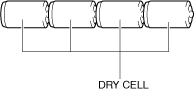
3. Prepare four dry cell batteries (1.5 V)
4. Connect the four dry cell batteries in a series.
ac5wzw00005108
|
5. Connect the positive pole of the dry cell battery to rear mount camera terminal A, and the negative pole to terminal D.
ac5wzw00015149
|
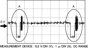
6. With the cell batteries being connected, measure the waveform between rear mount camera terminal C and terminal D.
7. Verify that waveform A shown in the figure is displayed two times or more.
ac5wzw00010245
|
8. If the voltage is not as shown in the figure, replace the rear mount camera.
Predicted Vehicle Path Assist Lines Display Type
1. Disconnect the negative battery terminal. (See NEGATIVE BATTERY TERMINAL DISCONNECTION/CONNECTION.)
2. Remove the following parts:
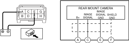
3. Connect the battery positive voltage to rear mount camera terminal A and connect terminal E to ground.
ac5wzw00015150
|
4. With the cell batteries being connected, measure the waveform between rear mount camera terminal C and terminal E.
5. Verify that waveform A shown in the figure is displayed two times or more.
ac5wzw00010245
|
6. If the voltage is not as shown in the figure, replace the rear mount camera.
With 360°view monitor system
1. Disconnect the negative battery terminal. (See NEGATIVE BATTERY TERMINAL DISCONNECTION/CONNECTION.)
2. Remove the following parts:
3. Prepare four dry cell batteries (1.5 V)
4. Connect the four dry cell batteries in a series.
ac5wzw00005108
|
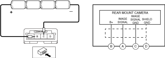
5. Connect the positive pole of the dry cell battery to rear mount camera terminal B, and the negative pole to terminal C.
ac5wzw00015152
|
6. With the cell batteries being connected, measure the waveform between rear mount camera terminal A and terminal C.
7. Verify that waveform A shown in the figure is displayed two times or more.
ac5wzw00010245
|
8. If the voltage is not as shown in the figure, replace the rear mount camera.
Type-B
1. Connect the M-MDS to the DLC-2.
2. Perform the DTC inspection for the connectivity master unit (CMU) and verify if any DTCs related to the rear mount camera is detected.(Without 360°VIEW MONITOR SYSTEM) (See DTC INSPECTION.)
3. Perform the DTC inspection for the 360°view monitor control module and verify if any DTCs related to the rear mount camera is detected. (With 360°VIEW MONITOR SYSTEM) (See DTC INSPECTION.)