ac5uun00002862
|
MULTIPLEX COMMUNICATION SYSTEM [TYPE-B]
id100048001400
Outline
ac5uun00002862
|
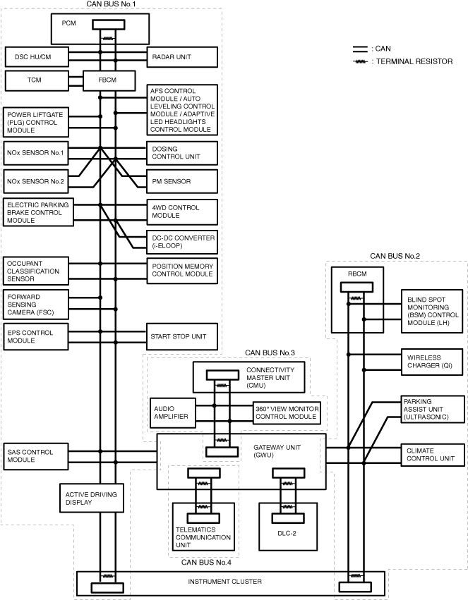
System Wiring Diagram
CAN communication (L.H.D.)
ac5wzn00005871
|
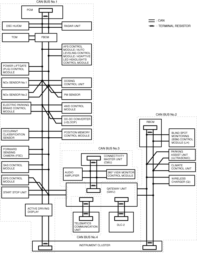
CAN communication (R.H.D.)
ac5wzn00005872
|
Local CAN
ac9uun00003600
|
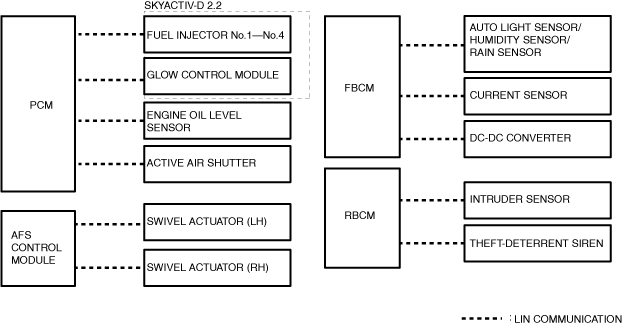
LIN communication
ac5wzn00005649
|
ISO communication
ac5uun00004588
|
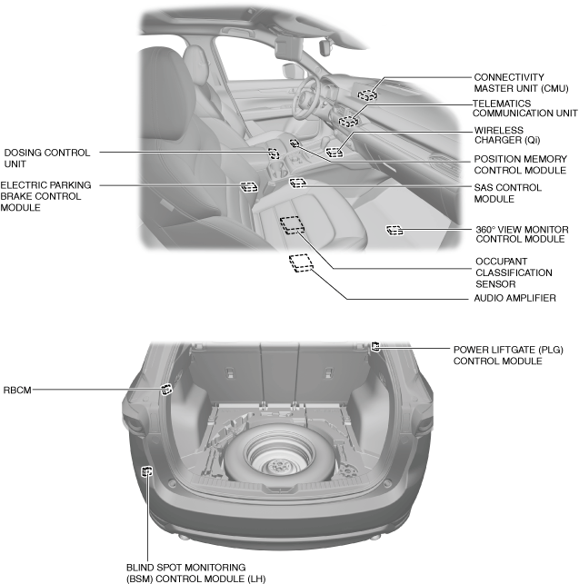
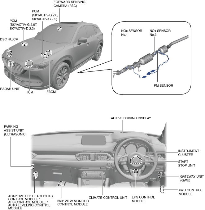
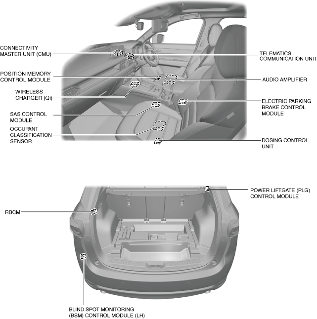
Structural View
L.H.D.
ac5wzn00005650
|
ac5wzn00005873
|
R.H.D.
ac5wzn00005651
|
ac5wzn00005652
|
Function
CAN (controller area network) system
Local CAN
LIN communication
ISO communication
Construction
CAN
Local CAN
LIN communication
ISO communication