|
1
|
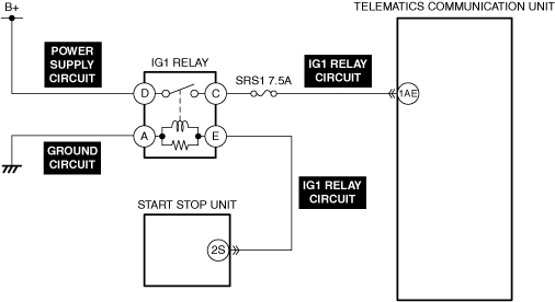
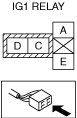
INSPECT IG1 RELAY FOR MALFUNCTION
• Inspect the applicable part. (Refer to the [RELAY INSPECTION] in the workshop manual)
• Is the part normal?
|
Yes
|
Go to the next step.
|
|
No
|
Repair or replace the malfunctioning location and perform the repair completion verification.
(Refer to the [RELAY LOCATION] in the workshop manual)
|
|
2
|
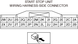
INSPECT START STOP UNIT FOR MALFUNCTION
• Perform the DTC inspection for the start stop unit. (Refer to the [DTC INSPECTION] in the workshop manual)
• Is a DTC displayed?
|
Yes
|
Repair the malfunctioning location according to the applicable DTC troubleshooting.
(Refer to the [DTC TABLE [START STOP UNIT]] in the workshop manual)
|
|
No
|
Go to the next step.
|
|
3
|
INSPECT PCM FOR MALFUNCTION
• Perform the DTC inspection for the PCM. (Refer to the [DTC INSPECTION] in the workshop manual)
• Is a DTC displayed?
|
Yes
|
Repair the malfunctioning location according to the applicable DTC troubleshooting.
(Refer to the [DTC TABLE [PCM (SKYACTIV-G)]] in the workshop manual)
(Refer to the [DTC TABLE [PCM (SKYACTIV-D)]] in the workshop manual)
|
|
No
|
Go to the next step.
|
|
4
|
INSPECT BATTERY FOR MALFUNCTION
• Inspect the applicable part. (Refer to the [BATTERY INSPECTION] in the workshop manual)
• Is the part normal?
|
Yes
|
Go to the next step.
|
|
No
|
Repair or replace the malfunctioning location and perform the repair completion verification.
(Refer to the [BATTERY RECHARGING] in the workshop manual)
(Refer to the [BATTERY REMOVAL/INSTALLATION] in the workshop manual)
|
|
5
|
INSPECT GENERATOR FOR MALFUNCTION
• Inspect the applicable part. (Refer to the [GENERATOR INSPECTION] in the workshop manual)
• Is the part normal?
|
Yes
|
Go to the next step.
|
|
No
|
Repair or replace the malfunctioning location and perform the repair completion verification.
(Refer to the [GENERATOR REMOVAL/INSTALLATION] in the workshop manual)
|
|
6
|
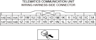
INSPECT TELEMATICS COMMUNICATION UNIT CONNECTOR FOR MALFUNCTION
• Inspect the applicable connector and terminal. (Refer to the [CONNECTOR INSPECTION] in the workshop manual)
• Are the connector and terminal normal?
|
Yes
|
Go to the next step.
|
|
No
|
Repair or replace the malfunctioning location and perform the repair completion verification.
|
|
7
|
INSPECT TELEMATICS COMMUNICATION UNIT IG1 RELAY CIRCUIT FOR SHORT TO GROUND AND OPEN CIRCUIT
• Inspect the applicable circuit for a short to ground and open circuit. (Refer to the [CIRCUIT INSPECTION] in the workshop manual)
• Is the circuit normal?
|
Yes
|
Go to the next step.
|
|
No
|
Repair or replace the malfunctioning location and perform the repair completion verification.
|
|
Repair completion verification 1
|
VERIFY THAT VEHICLE IS REPAIRED
• Install/connect the part removed/disconnected during the troubleshooting procedure.
• Clear the DTC recorded in the memory. (Refer to the [CLEARING DTC] in the workshop manual)
• Switch the ignition ON (engine off or on) and wait for 10 s or more.
• Perform the DTC inspection for the telematics communication unit. (Refer to the [DTC INSPECTION] in the workshop manual)
• Is the same Pending DTC present?
|
Yes
|
Refer to the controller area network (CAN) malfunction diagnosis flow to inspect for a CAN communication error.
(Refer to the [CONTROLLER AREA NETWORK (CAN) MALFUNCTION DIAGNOSIS FLOW] in the workshop manual)
If the CAN communication is normal, perform the diagnosis from Step 1.
• If the malfunction recurs, replace the telematics communication unit, then go to the next step. (Refer to the [TELEMATICS COMMUNICATION UNIT REMOVAL/INSTALLATION] in the workshop manual)
|
|
No
|
Go to the next step.
|
|
Repair completion verification 2
|
VERIFY IF OTHER DTC IS DISPLAYED
• Perform the DTC inspection. (Refer to the [DTC INSPECTION] in the workshop manual)
• Are any other DTCs displayed?
|
Yes
|
Repair the malfunctioning location according to the applicable DTC troubleshooting.
|
|
No
|
DTC troubleshooting completed.
|