|
1
|
VERIFY PCM DTCs
• Retrieve the PCM DTCs using the M-MDS. (Refer to the [ON-BOARD DIAGNOSTIC TEST [PCM (SKYACTIV-G)]] in the workshop manual)
(Refer to the [ON-BOARD DIAGNOSTIC TEST [PCM (SKYACTIV-D)]] in the workshop manual)
• Are any DTCs displayed?
|
Yes
|
Repair or replace the malfunctioning part according to the applicable DTC troubleshooting.
(Refer to the [DTC TABLE [PCM (SKYACTIV-G)]] in the workshop manual)
(Refer to the [DTC TABLE [PCM (SKYACTIV-D]] in the workshop manual)
|
|
No
|
Go to the next step.
|
|
2
|
INSPECT BATTERY
• Inspect the battery. (Refer to the [BATTERY INSPECTION] in the workshop manual)
• Is the battery normal?
|
Yes
|
Go to the next step.
|
|
No
|
Recharge or replace the battery, then go to Step 8.
(Refer to the [BATTERY RECHARGING] in the workshop manual)
(Refer to the [BATTERY REMOVAL/INSTALLATION] in the workshop manual)
|
|
3
|
INSPECT GENERATOR
• Inspect the generator. (Refer to the [GENERATOR INSPECTION] in the workshop manual)
• Is the generator normal?
|
Yes
|
Go to the next step.
|
|
No
|
Replace the generator, then go to Step 8.
(Refer to the [GENERATOR REMOVAL/INSTALLATION] in the workshop manual)
|
|
4
|
INSPECT TUNER AND AMP UNIT (TAU) CONNECTOR CONDITION
• Switch the ignition off.
• Disconnect the negative battery terminal. (Refer to the [NEGATIVE BATTERY TERMINAL DISCONNECTION/CONNECTION] in the workshop manual)
• Disconnect the tuner and amp unit (TAU) connector.
• Inspect the connector engagement and connection condition and inspect the terminals for damage, deformation, corrosion, or disconnection.
• Is the connector normal?
|
Yes
|
Go to the next step.
|
|
No
|
Repair or replace the connector, then go to Step 8.
|
|
5
|
INSPECT DC-DC CONVERTER (i-ELOOP) CONNECTOR CONDITION
• Disconnect the DC-DC converter (i-ELOOP) connector.
• Inspect the connector engagement and connection condition and inspect the terminals for damage, deformation, corrosion, or disconnection.
• Is the connector normal?
|
Yes
|
Go to the next step.
|
|
No
|
Repair or replace the connector, then go to Step 8.
|
|
6
|
VERIFY TUNER AND AMP UNIT (TAU) POWER SUPPLY VOLTAGE
• Verify that the tuner and amp unit (TAU) connector is disconnected.
• Connect the negative battery terminal. (Refer to the [NEGATIVE BATTERY TERMINAL DISCONNECTION/CONNECTION] in the workshop manual)
• Switch the ignition ON (engine off or on).
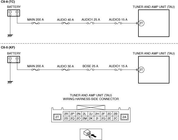
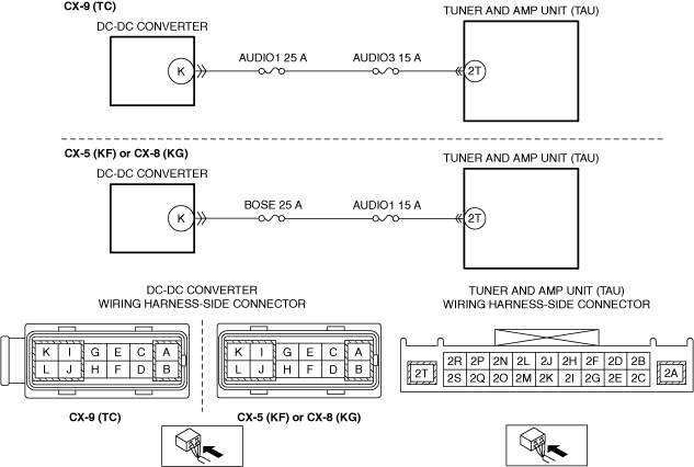
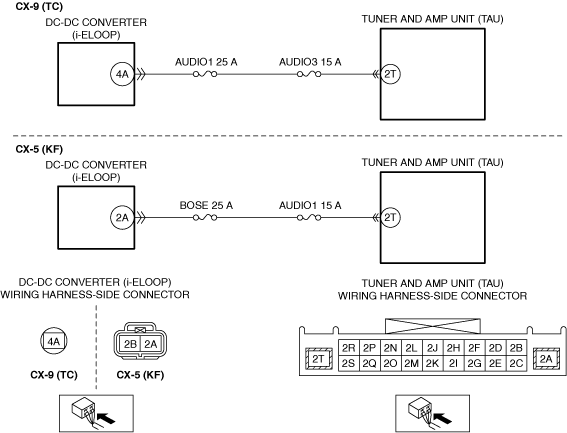
• Measure the voltage at tuner and amp unit (TAU) terminal 2T (wiring harness-side).
• Is the voltage 10 V or more?
|
Yes
|
Go to the next step.
|
|
No
|
Inspect the AUDIO3 15 A fuse (CX-9 (TC)), AUDIO1 25 A fuse (CX-9 (TC)), AUDIO1 15 A fuse (CX-5 (KF)) and BOSE 25 A fuse (CX-5 (KF)).
• Any fuse is blown:
-
― Refer to the wiring diagram and verify if there is a common connector between the following terminals:
-
• AUDIO1 25 A fuse—Tuner and amp unit (TAU) terminal 2T (CX-9 (TC))
• BOSE 25 A fuse—Tuner and amp unit (TAU) terminal 2T (CX-5 (KF))
If there is a common connector:
-
• Determine the malfunctioning part by inspecting the common connector and the terminal for corrosion, damage, or pin disconnection, and the common wiring harness for a short to ground.
• Repair or replace the malfunctioning location.
If there is no common connector:
-
• Repair or replace the wiring harness which has a short to ground.
• Replace the fuse.
• Any fuse is damaged:
-
― Replace the fuse.
• All fuses are normal:
-
― Refer to the wiring diagram and verify if there is a common connector between the following terminals:
-
• DC-DC converter (i-ELOOP) terminal 4A—Tuner and amp unit (TAU) terminal 2T (CX-9 (TC))
• DC-DC converter (i-ELOOP) terminal 2A—Tuner and amp unit (TAU) terminal 2T (CX-5 (KF))
If there is a common connector:
-
• Determine the malfunctioning part by inspecting the common connector and the terminal for corrosion, damage, or pin disconnection, and the common wiring harness for an open circuit.
• Repair or replace the malfunctioning location.
If there is no common connector:
-
• Repair or replace the wiring harness which has an open circuit.
Go to Step 8.
|
|
7
|
INSPECT DC-DC CONVERTER (i-ELOOP)
• Inspect the DC-DC converter (i-ELOOP). (Refer to the [DC-DC CONVERTER (i-ELOOP) INSPECTION [i-ELOOP]] in the workshop manual)
• Is the DC-DC converter normal?
|
Yes
|
Go to the next step.
|
|
No
|
Replace the DC-DC converter (i-ELOOP), then go to the next step.
(Refer to the [DC-DC CONVERTER (i-ELOOP) REMOVAL/INSTALLATION [i-ELOOP]] in the workshop manual)
|
|
8
|
VERIFY THAT REPAIRS HAVE BEEN COMPLETED
• Always reconnect all disconnected connectors.
• Connect the negative battery terminal. (Refer to the [NEGATIVE BATTERY TERMINAL DISCONNECTION/CONNECTION] in the workshop manual)
• Clear the DTC for the connectivity master unit (CMU) using the M-MDS.
• Switch the ignition ON (engine off or on) and wait for 17 s or more.
• Retrieve the connectivity master unit (CMU) DTCs using the M-MDS.
• Is the same Pending DTC present?
|
Yes
|
Repeat the inspection from Step 1.
• If the malfunction recurs, replace the tuner and amp unit (TAU). (Refer to the [TUNER AND AMP UNIT (TAU) REMOVAL/INSTALLATION] in the workshop manual)
Go to the next step.
|
|
No
|
Go to the next step.
|
|
9
|
VERIFY IF OTHER DTCs DISPLAYED
• Are any other DTCs displayed?
|
Yes
|
Repair or replace the malfunctioning part according to the applicable DTC troubleshooting.
|
|
No
|
DTC troubleshooting completed.
|