DTC B12BD:87 [CONNECTIVITY MASTER UNIT (TYPE-A)]
id1602a8014900
Without 360° View Monitor System
Description |
Rear mount camera transmission error |
---|---|
Detection condition
|
• The connectivity master unit (CMU) cannot receive a signal from the rear mount camera for 5 s or more with the ignition switched ON (engine off or on).
|
Fail-safe
|
Not applicable
|
Possible cause
|
• Rear mount camera connector or terminal malfunction
• Connectivity master unit (CMU) connector or terminal malfunction
• Short to ground in wiring harness between connectivity master unit (CMU) terminal 1A and rear mount camera terminal C
• Short to power supply in wiring harness between connectivity master unit (CMU) terminal 1A and rear mount camera terminal C
• Open circuit in wiring harness between connectivity master unit (CMU) terminal 1A and rear mount camera terminal C
• Rear mount camera malfunction
• Connectivity master unit (CMU) malfunction
|
![]() |
Diagnostic Procedure
Step |
Inspection |
Action |
|
---|---|---|---|
1
|
INSPECT REAR MOUNT CAMERA CONNECTOR CONDITION
• Switch the ignition off.
• Disconnect the negative battery terminal.
(Refer to the [NEGATIVE BATTERY TERMINAL DISCONNECTION/CONNECTION] in the workshop manual)
• Disconnect the rear mount camera connector.
• Inspect the connector engagement and connection condition and inspect the terminals for damage, deformation, corrosion, or disconnection.
• Is the connector normal?
|
Yes
|
Go to the next step.
|
No
|
Repair or replace the connector, then go to Step 7.
|
||
2
|
INSPECT CONNECTIVITY MASTER UNIT (CMU) CONNECTOR CONDITION
• Disconnect the connectivity master unit (CMU) connector.
• Inspect the connector engagement and connection condition and inspect the terminals for damage, deformation, corrosion, or disconnection.
• Is the connector normal?
|
Yes
|
Go to the next step.
|
No
|
Repair or replace the connector, then go to Step 7.
|
||
3
|
INSPECT REAR MOUNT CAMERA CIRCUIT FOR SHORT TO GROUND
• Verify that the rear mount camera and connectivity master unit (CMU) connectors are disconnected.
• Inspect for continuity between rear mount camera terminal C (wiring harness-side) and body ground.
• Is there continuity?
|
Yes
|
Refer to the wiring diagram and verify if there is a common connector between connectivity master unit (CMU) terminal 1A and rear mount camera terminal C.
If there is a common connector:
• Determine the malfunctioning part by inspecting the common connector and the terminal for corrosion, damage, or pin disconnection, and the common wiring harness for a short to ground.
• Repair or replace the malfunctioning location.
If there is no common connector:
• Repair or replace the wiring harness which has a short to ground.
Go to Step 7.
|
No
|
Go to the next step.
|
||
4
|
INSPECT REAR MOUNT CAMERA CIRCUIT FOR SHORT TO POWER SUPPLY
• Verify that the rear mount camera and connectivity master unit (CMU) connectors are disconnected.
• Connect the negative battery terminal.
(Refer to the [NEGATIVE BATTERY TERMINAL DISCONNECTION/CONNECTION] in the workshop manual)
• Switch the ignition ON (engine off or on).
• Measure the voltage at rear mount camera terminal C (wiring harness-side).
• Is the voltage 0 V?
|
Yes
|
Go to the next step.
|
No
|
Refer to the wiring diagram and verify if there is a common connector between connectivity master unit (CMU) terminal 1A and rear mount camera terminal C.
If there is a common connector:
• Determine the malfunctioning part by inspecting the common connector and the terminal for corrosion, damage, or pin disconnection, and the common wiring harness for a short to power supply.
• Repair or replace the malfunctioning location.
If there is no common connector:
• Repair or replace the wiring harness which has a short to power supply.
Go to Step 7.
|
||
5
|
INSPECT REAR MOUNT CAMERA CIRCUIT FOR OPEN CIRCUIT
• Switch the ignition off.
• Disconnect the negative battery terminal.
(Refer to the [NEGATIVE BATTERY TERMINAL DISCONNECTION/CONNECTION] in the workshop manual)
• Verify that the rear mount camera and connectivity master unit (CMU) connectors are disconnected.
• Inspect the wiring harness for continuity between connectivity master unit (CMU) terminal 1A (wiring harness-side) and rear mount camera terminal C (wiring harness-side).
• Is there continuity?
|
Yes
|
Go to the next step.
|
No
|
Refer to the wiring diagram and verify if there is a common connector between connectivity master unit (CMU) terminal 1A and rear mount camera terminal C.
If there is a common connector:
• Determine the malfunctioning part by inspecting the common connector and the terminal for corrosion, damage, or pin disconnection, and the common wiring harness for an open circuit.
• Repair or replace the malfunctioning location.
If there is no common connector:
• Repair or replace the wiring harness which has an open circuit.
Go to Step 7.
|
||
6
|
VERIFY IF MALFUNCTIONING LOCATION IS REAR MOUNT CAMERA DEPENDING ON REPEATABILITY
• Always reconnect all disconnected connectors.
• Connect the negative battery terminal.
(Refer to the [NEGATIVE BATTERY TERMINAL DISCONNECTION/CONNECTION] in the workshop manual)
• Clear the DTC for the connectivity master unit (CMU) using the M-MDS.
• Switch the ignition ON (engine off or on) and wait for 12 s or more.
• Retrieve the connectivity master unit (CMU) DTCs using the M-MDS.
• Is the same Pending DTC present?
|
Yes
|
Replace the rear mount camera, then go to the next step.
(Refer to the [REAR MOUNT CAMERA REMOVAL/INSTALLATION] in the workshop manual)
|
No
|
Go to Step 8.
|
||
7
|
VERIFY THAT REPAIRS HAVE BEEN COMPLETED
• Always reconnect all disconnected connectors.
• Connect the negative battery terminal.
(Refer to the [NEGATIVE BATTERY TERMINAL DISCONNECTION/CONNECTION] in the workshop manual)
• Clear the DTC for the connectivity master unit (CMU) using the M-MDS.
• Switch the ignition ON (engine off or on) and wait for 12 s or more.
• Retrieve the connectivity master unit (CMU) DTCs using the M-MDS.
• Is the same Pending DTC present?
|
Yes
|
Repeat the inspection from Step 1.
• If the malfunction recurs, replace the connectivity master unit (CMU).
(Refer to the [CONNECTIVITY MASTER UNIT (CMU) REMOVAL/INSTALLATION] in the workshop manual)
Go to the next step.
|
No
|
Go to the next step.
|
||
8
|
VERIFY IF OTHER DTCs DISPLAYED
• Are any other DTCs displayed?
|
Yes
|
Repair or replace the malfunctioning part according to the applicable DTC troubleshooting.
|
No
|
DTC troubleshooting completed.
|
With 360° View Monitor System
Description |
Communication error with 360° view monitor control module |
---|---|
Detection condition
|
• The connectivity master unit (CMU) cannot receive a signal from the 360° view monitor control module for 5 s or more with the ignition switched ON (engine off or on).
|
Fail-safe
|
Not applicable
|
Possible cause
|
• DTCs are stored in the 360° view monitor control module.
• 360° view monitor control module connector or terminal malfunction
• Connectivity master unit (CMU) connector or terminal malfunction
• Short to ground in wiring harness between connectivity master unit (CMU) terminal 1A and 360° view monitor control module terminal I
• Short to power supply in wiring harness between connectivity master unit (CMU) terminal 1A and 360° view monitor control module terminal I
• Open circuit in wiring harness between connectivity master unit (CMU) terminal 1A and 360° view monitor control module terminal I
• 360° view monitor control module malfunction
• Connectivity master unit (CMU) malfunction
|
![]() |
Diagnostic Procedure
Step |
Inspection |
Action |
|
---|---|---|---|
1
|
VERIFY 360° VIEW MONITOR CONTROL MODULE DTCS
• Perform the DTC inspection for the 360° view monitor control module using the M-MDS.
(Refer to the [DTC INSPECTION [360° VIEW MONITOR CONTROL MODULE]] in the workshop manual)
• Are any DTCs displayed?
|
Yes
|
Repair the malfunctioning location according to the applicable DTC troubleshooting.
(Refer to the [DTC TABLE [360° VIEW MONITOR CONTROL MODULE]] in the workshop manual)
|
No
|
Go to the next step.
|
||
2
|
INSPECT 360° VIEW MONITOR CONTROL MODULE CONNECTOR CONDITION
• Switch the ignition off.
• Disconnect the negative battery terminal.
(Refer to the [NEGATIVE BATTERY TERMINAL DISCONNECTION/CONNECTION] in the workshop manual)
• Disconnect the 360° view monitor control module connector.
• Inspect the connector engagement and connection condition and inspect the terminals for damage, deformation, corrosion, or disconnection.
• Is the connector normal?
|
Yes
|
Go to the next step.
|
No
|
Repair or replace the connector, then go to Step 8.
|
||
3
|
INSPECT CONNECTIVITY MASTER UNIT (CMU) CONNECTOR CONDITION
• Disconnect the connectivity master unit (CMU) connector.
• Inspect the connector engagement and connection condition and inspect the terminals for damage, deformation, corrosion, or disconnection.
• Is the connector normal?
|
Yes
|
Go to the next step.
|
No
|
Repair or replace the connector, then go to Step 8.
|
||
4
|
INSPECT 360° VIEW MONITOR CONTROL MODULE CIRCUIT FOR SHORT TO GROUND
• Verify that the 360° view monitor control module and connectivity master unit (CMU) connectors are disconnected.
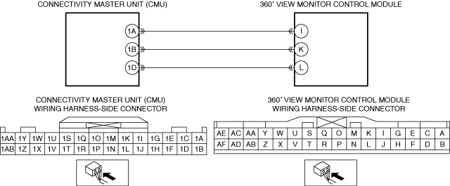
• Inspect for continuity between 360° view monitor control module terminal I (wiring harness-side) and body ground.
• Is there continuity?
|
Yes
|
Refer to the wiring diagram and verify if there is a common connector between connectivity master unit (CMU) terminal 1A and 360° view monitor control module terminal I.
If there is a common connector:
• Determine the malfunctioning part by inspecting the common connector and the terminal for corrosion, damage, or pin disconnection, and the common wiring harness for a short to ground.
• Repair or replace the malfunctioning location.
If there is no common connector:
• Repair or replace the wiring harness which has a short to ground.
Go to Step 8.
|
No
|
Go to the next step.
|
||
5
|
INSPECT 360° VIEW MONITOR CONTROL MODULE CIRCUIT FOR SHORT TO POWER SUPPLY
• Verify that the 360° view monitor control module and connectivity master unit (CMU) connectors are disconnected.
• Connect the negative battery terminal.
(Refer to the [NEGATIVE BATTERY TERMINAL DISCONNECTION/CONNECTION] in the workshop manual)
• Switch the ignition ON (engine off or on).
• Measure the voltage at 360° view monitor control module terminal I (wiring harness-side).
• Is the voltage 0 V?
|
Yes
|
Go to the next step.
|
No
|
Refer to the wiring diagram and verify if there is a common connector between connectivity master unit (CMU) terminal 1A and 360° view monitor control module terminal I.
If there is a common connector:
• Determine the malfunctioning part by inspecting the common connector and the terminal for corrosion, damage, or pin disconnection, and the common wiring harness for a short to power supply.
• Repair or replace the malfunctioning location.
If there is no common connector:
• Repair or replace the wiring harness which has a short to power supply.
Go to Step 8.
|
||
6
|
INSPECT 360° VIEW MONITOR CONTROL MODULE CIRCUIT FOR OPEN CIRCUIT
• Switch the ignition off.
• Disconnect the negative battery terminal.
(Refer to the [NEGATIVE BATTERY TERMINAL DISCONNECTION/CONNECTION] in the workshop manual)
• Verify that the 360° view monitor control module and connectivity master unit (CMU) connectors are disconnected.
• Inspect the wiring harness for continuity between connectivity master unit (CMU) terminal 1A (wiring harness-side) and 360° view monitor control module terminal I (wiring harness-side).
• Is there continuity?
|
Yes
|
Go to the next step.
|
No
|
Refer to the wiring diagram and verify if there is a common connector between connectivity master unit (CMU) terminal 1A and 360° view monitor control module terminal I.
If there is a common connector:
• Determine the malfunctioning part by inspecting the common connector and the terminal for corrosion, damage, or pin disconnection, and the common wiring harness for an open circuit.
• Repair or replace the malfunctioning location.
If there is no common connector:
• Repair or replace the wiring harness which has an open circuit.
Go to Step 8.
|
||
7
|
VERIFY IF MALFUNCTIONING LOCATION IS 360° VIEW MONITOR CONTROL MODULE DEPENDING ON REPEATABILITY
• Always reconnect all disconnected connectors.
• Connect the negative battery terminal.
(Refer to the [NEGATIVE BATTERY TERMINAL DISCONNECTION/CONNECTION] in the workshop manual)
• Clear the DTC for the connectivity master unit (CMU) using the M-MDS.
• Switch the ignition ON (engine off or on) and wait for 12 s or more.
• Retrieve the connectivity master unit (CMU) DTCs using the M-MDS.
• Is the same Pending DTC present?
|
Yes
|
Replace the 360° view monitor control module, then go to the next step.
(Refer to the [360° VIEW MONITOR CONTROL MODULE REMOVAL/INSTALLATION] in the workshop manual)
|
No
|
Go to Step 9.
|
||
8
|
VERIFY THAT REPAIRS HAVE BEEN COMPLETED
• Always reconnect all disconnected connectors.
• Connect the negative battery terminal.
(Refer to the [NEGATIVE BATTERY TERMINAL DISCONNECTION/CONNECTION] in the workshop manual)
• Clear the DTC for the connectivity master unit (CMU) using the M-MDS.
• Switch the ignition ON (engine off or on) and wait for 12 s or more.
• Retrieve the connectivity master unit (CMU) DTCs using the M-MDS.
• Is the same Pending DTC present?
|
Yes
|
Repeat the inspection from Step 1.
• If the malfunction recurs, replace the connectivity master unit (CMU).
(Refer to the [CONNECTIVITY MASTER UNIT (CMU) REMOVAL/INSTALLATION] in the workshop manual)
Go to the next step.
|
No
|
Go to the next step.
|
||
9
|
VERIFY IF OTHER DTCs DISPLAYED
• Are any other DTCs displayed?
|
Yes
|
Repair or replace the malfunctioning part according to the applicable DTC troubleshooting.
|
No
|
DTC troubleshooting completed.
|