DTC B119F:13 [CONNECTIVITY MASTER UNIT (TYPE-B)]


id1602a9000300


Without Telematics Communication System


Outline

System malfunction location

GPS antenna signal circuit malfunction

Detection condition
•  The connectivity master unit (CMU) detects a short to power supply or open circuit in the GPS antenna signal circuit.
Fail-safe
Not applicable
Possible cause
•  GPS antenna connector or terminal malfunction
•  Malfunction in connectivity master unit (CMU) connector or terminal
•  GPS antenna feeder malfunction
―  Short to power supply in GPS antenna signal circuit
―  Open circuit in GPS antenna signal circuit
•  GPS antenna malfunction
•  Connectivity master unit (CMU) malfunction


Diagnostic procedure

Step

Inspection

Results

Action

1
VERIFY IF GNSS INFORMATION CAN BE RECEIVED
•  Switch the ignition ON (engine off) and display the navigation screen of the center display
•  Is the current position displayed?
Yes
Verify that the repairs have been completed.
No
Go to the next step.
2
VERIFY GNSS INFORMATION RECEPTION CONDITION
Note
•  If there is no response, move the vehicle outside (in environment where radio signal is not interrupted or obstructed) and verify the display again.
•  Perform the [Navigation System Inspection] using the diagnostic assist function.
•  Verify the number of receptions display for [GPS+GLONASS+QZSS] on the inspection result screen.
•  Is the number of receptions 1 or more?
Yes
Verify that the repairs have been completed.
No
Go to the next step.
3
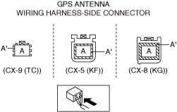
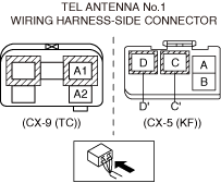
INSPECT GPS ANTENNA CONNECTOR FOR MALFUNCTION
•  Inspect the applicable connector and terminal.
(Refer to the [CONNECTOR INSPECTION] in the workshop manual)
•  Are the connector and terminal normal?
Yes
Go to the next step.
No
Repair or replace the malfunctioning location and perform the repair completion verification.
4
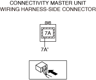
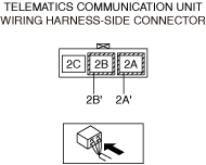
INSPECT CONNECTIVITY MASTER UNIT (CMU) CONNECTOR FOR MALFUNCTION
•  Inspect the applicable connector and terminal.
(Refer to the [CONNECTOR INSPECTION] in the workshop manual)
•  Are the connector and terminal normal?
Yes
Go to the next step.
No
Repair or replace the malfunctioning location and perform the repair completion verification.
5
INSPECT GPS ANTENNA POWER SUPPLY VOLTAGE
•  Verify that the GPS antenna connector is disconnected.
•  Connect the connectivity master unit (CMU) connector.
•  Connect the negative battery terminal.
(Refer to the [NEGATIVE BATTERY TERMINAL DISCONNECTION/CONNECTION] in the workshop manual)
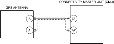
•  Measure the voltage at GPS antenna terminal A (wiring harness-side).
•  Is the voltage between 4.1—5.1 V?
Yes
Go to the next step.
No
Repair or replace the malfunctioning location and perform the repair completion verification.
(Refer to the [GLOBAL POSITIONING SYSTEM (GPS) ANTENNA REMOVAL/INSTALLATION] in the workshop manual)
6
INSPECT CONNECTIVITY MASTER UNIT (CMU) POWER SUPPLY VOLTAGE
•  Verify that the GPS antenna connector is disconnected.
•  Measure the voltage at connectivity master unit (CMU) terminal 7A (wiring harness-side).
•  Is the voltage between 4.1—5.1 V?
Yes
Repair or replace the malfunctioning location and perform the repair completion verification.
(Refer to the [GLOBAL POSITIONING SYSTEM (GPS) ANTENNA FEEDER REMOVAL/INSTALLATION] in the workshop manual)
No
Go to the next step.
7
DETERMINE MALFUNCTIONING LOCATION
Note
•  If there is no response, move the vehicle outside (in environment where radio signal is not interrupted or obstructed) and verify the display again.
•  Perform the [Navigation System Inspection] using the diagnostic assist function.
•  Verify the number of receptions display for [GPS+GLONASS+QZSS] on the inspection result screen.
•  Is the number of receptions 1 or more?
Yes
Verify that the repairs have been completed.
No
Refer to the controller area network (CAN) malfunction diagnosis flow to inspect for a CAN communication error.
(Refer to the [CONTROLLER AREA NETWORK (CAN) MALFUNCTION DIAGNOSIS FLOW] in the workshop manual)
If the CAN communication is normal, perform the diagnosis from Step 1.
•  If the malfunction recurs, replace the connectivity master unit (CMU), then perform the repair completion verification.
(Refer to the [CONNECTIVITY MASTER UNIT (CMU) REMOVAL/INSTALLATION] in the workshop manual)
Repair completion verification 1
VERIFY THAT VEHICLE IS REPAIRED
•  Install/connect the part removed/disconnected during the troubleshooting procedure.
•  Clear the DTC recorded in the memory.
(Refer to the [CLEARING DTC] in the workshop manual)
•  Perform the DTC inspection for the connectivity master unit (CMU).
(Refer to the [DTC INSPECTION] in the workshop manual)
•  Is the same Pending DTC present?
Yes
Refer to the controller area network (CAN) malfunction diagnosis flow to inspect for a CAN communication error.
(Refer to the [CONTROLLER AREA NETWORK (CAN) MALFUNCTION DIAGNOSIS FLOW] in the workshop manual)
If the CAN communication is normal, perform the diagnosis from Step 1.
•  If the malfunction recurs, replace the connectivity master unit (CMU), then go to the next step.
(Refer to the [CONNECTIVITY MASTER UNIT (CMU) REMOVAL/INSTALLATION] in the workshop manual)
No
Go to the next step.
Repair completion verification 2
VERIFY IF OTHER DTCs ARE DISPLAYED
•  Perform the DTC inspection.
(Refer to the [DTC INSPECTION] in the workshop manual)
•  Is a DTC displayed?
Yes
Repair the malfunctioning location according to the applicable DTC troubleshooting.
No
DTC troubleshooting completed.


With Telematics Communication System


Outline

System malfunction location

TEL antenna No.1 signal circuit malfunction

Detection condition
•  The connectivity master unit (CMU) detects a short to power supply or open circuit in the TEL antenna No.1 signal circuit.
Fail-safe
Not applicable
Possible cause
•  TEL antenna No.1 connector or terminal malfunction
•  Telematics communication unit connector or terminal malfunction
•  Short to power supply in TEL antenna No.1 signal circuit
•  Open circuit in TEL antenna No.1 signal circuit
•  TEL antenna No.1 malfunction
•  Telematics communication unit malfunction
•  Connectivity master unit (CMU) malfunction


Diagnostic procedure

Step

Inspection

Results

Action

1
VERIFY IF GNSS INFORMATION CAN BE RECEIVED
•  Switch the ignition ON (engine off) and display the navigation screen of the center display
•  Is the current position displayed?
Yes
Verify that the repairs have been completed.
No
Go to the next step.
2
VERIFY GNSS INFORMATION RECEPTION CONDITION
Note
•  If there is no response, move the vehicle outside (in environment where radio signal is not interrupted or obstructed) and verify the display again.
•  Perform the [Navigation System Inspection] using the diagnostic assist function.
•  Verify the number of receptions display for [GPS+GLONASS+QZSS] on the inspection result screen.
•  Is the number of receptions 1 or more?
Yes
Verify that the repairs have been completed.
No
Go to the next step.
3
INSPECT TEL ANTENNA No.1 CONNECTOR FOR MALFUNCTION
•  Inspect the applicable connector and terminal.
(Refer to the [CONNECTOR INSPECTION] in the workshop manual)
•  Are the connector and terminal normal?
Yes
Go to the next step.
No
Repair or replace the malfunctioning location and perform the repair completion verification.
4
INSPECT TELEMATICS COMMUNICATION UNIT CONNECTOR FOR MALFUNCTION
•  Inspect the applicable connector and terminal.
(Refer to the [CONNECTOR INSPECTION] in the workshop manual)
•  Are the connector and terminal normal?
Yes
Go to the next step.
No
Repair or replace the malfunctioning location and perform the repair completion verification.
5
INSPECT TEL ANTENNA No.1 POWER SUPPLY VOLTAGE
•  Verify that the TEL antenna No.1 connector is disconnected.
•  Connect the telematics communication unit connector.
•  Connect the negative battery terminal.
(Refer to the [NEGATIVE BATTERY TERMINAL DISCONNECTION/CONNECTION] in the workshop manual)
•  Measure the voltage at the following terminals (wiring harness-side):
―  TEL antenna No.1 terminal A2 (CX-9 (TC))
―  TEL antenna No.1 terminal D (CX-5 (KF))
•  Is the voltage between 4.1—5.1 V?
Yes
Go to the next step.
No
Repair or replace the malfunctioning location and perform the repair completion verification.
(Refer to the [TEL ANTENNA REMOVAL/INSTALLATION] in the workshop manual)
6
INSPECT TELEMATICS COMMUNICATION UNIT POWER SUPPLY VOLTAGE
•  Verify that the TEL antenna No.1 connector is disconnected.
•  Measure the voltage at telematics communication unit terminal 2B (wiring harness-side).
•  Is the voltage between 4.1—5.1 V?
Yes
Repair or replace the wiring harness and perform the repair completion verification.
No
Go to the next step.
7
DETERMINE MALFUNCTIONING LOCATION
Note
•  If there is no response, move the vehicle outside (in environment where radio signal is not interrupted or obstructed) and verify the display again.
•  Perform the [Navigation System Inspection] using the diagnostic assist function.
•  Verify the number of receptions display for [GPS+GLONASS+QZSS] on the inspection result screen.
•  Is the number of receptions 1 or more?
Yes
Verify that the repairs have been completed.
No
Refer to the controller area network (CAN) malfunction diagnosis flow to inspect for a CAN communication error.
(Refer to the [CONTROLLER AREA NETWORK (CAN) MALFUNCTION DIAGNOSIS FLOW] in the workshop manual)
If the CAN communication is normal, perform the diagnosis from Step 1.
•  If the malfunction recurs, replace the telematics communication unit, then perform the repair completion verification.
(Refer to the [TELEMATICS COMMUNICATION UNIT REMOVAL/INSTALLATION] in the workshop manual)
Repair completion verification 1
VERIFY THAT VEHICLE IS REPAIRED
•  Install/connect the part removed/disconnected during the troubleshooting procedure.
•  Clear the DTC recorded in the memory.
(Refer to the [CLEARING DTC] in the workshop manual)
•  Perform the DTC inspection for the connectivity master unit (CMU).
(Refer to the [DTC INSPECTION] in the workshop manual)
•  Is the same Pending DTC present?
Yes
Refer to the controller area network (CAN) malfunction diagnosis flow to inspect for a CAN communication error.
(Refer to the [CONTROLLER AREA NETWORK (CAN) MALFUNCTION DIAGNOSIS FLOW] in the workshop manual)
If the CAN communication is normal, perform the diagnosis from Step 1.
•  If the malfunction recurs, replace the connectivity master unit (CMU), then go to the next step.
(Refer to the [CONNECTIVITY MASTER UNIT (CMU) REMOVAL/INSTALLATION] in the workshop manual)
No
Go to the next step.
Repair completion verification 2
VERIFY IF OTHER DTCs ARE DISPLAYED
•  Perform the DTC inspection.
(Refer to the [DTC INSPECTION] in the workshop manual)
•  Is a DTC displayed?
Yes
Repair the malfunctioning location according to the applicable DTC troubleshooting.
No
DTC troubleshooting completed.