|
1
|
INSPECT TUNER AND AMP UNIT (TAU) CONNECTOR
• Switch the ignition off.
• Disconnect the negative battery terminal. (Refer to the [NEGATIVE BATTERY TERMINAL DISCONNECTION/CONNECTION] in the workshop manual.)
• Disconnect the tuner and amp unit (TAU) connector.
• Inspect the connector engagement and connection condition and inspect the terminals for damage, deformation, corrosion, or disconnection.
• Is the connector normal?
|
Yes
|
Go to the next step.
|
|
No
|
Repair or replace the connector, then go to Step 7.
|
|
2
|
INSPECT CONNECTIVITY MASTER UNIT (CMU) CONNECTOR
• Disconnect the connectivity master unit (CMU) connector.
• Inspect the connector engagement and connection condition and inspect the terminals for damage, deformation, corrosion, or disconnection.
• Is the connector normal?
|
Yes
|
Go to the next step.
|
|
No
|
Repair or replace the connector, then go to Step 7.
|
|
3
|
VERIFY IF MALFUNCTION CAUSE IS OPEN CIRCUIT IN WIRING HARNESS BETWEEN CONNECTIVITY MASTER UNIT (CMU) AND TUNER AND AMP UNIT (TAU)
• Verify that the connectivity master unit (CMU) and tuner and amp unit (TAU) connectors are disconnected.
• Inspect the wiring harness for continuity between the following terminals (vehicle wiring harness side).
-
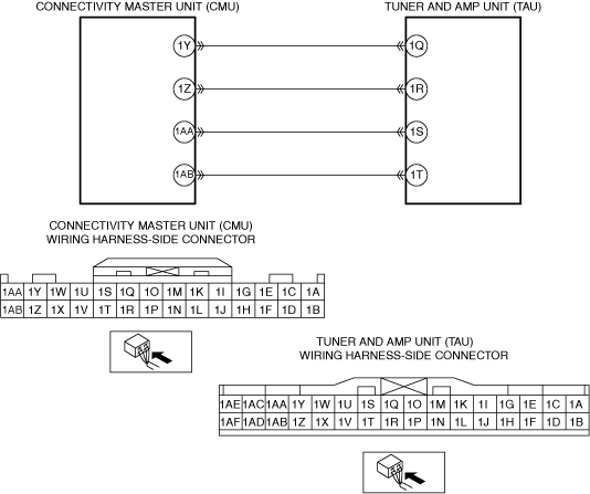
― Connectivity master unit (CMU) terminal 1Y—Tuner and amp unit (TAU) terminal 1Q
― Connectivity master unit (CMU) terminal 1Z—Tuner and amp unit (TAU) terminal 1R
― Connectivity master unit (CMU) terminal 1AA—Tuner and amp unit (TAU) terminal 1S
― Connectivity master unit (CMU) terminal 1AB—Tuner and amp unit (TAU) terminal 1T
• Is there continuity?
|
Yes
|
Go to the next step.
|
|
No
|
Refer to the wiring diagram and verify if there is a common connector between the following terminals.
• Connectivity master unit (CMU) terminal 1Y—Tuner and amp unit (TAU) terminal 1Q
• Connectivity master unit (CMU) terminal 1Z—Tuner and amp unit (TAU) terminal 1R
• Connectivity master unit (CMU) terminal 1AA—Tuner and amp unit (TAU) terminal 1S
• Connectivity master unit (CMU) terminal 1AB—Tuner and amp unit (TAU) terminal 1T
If there is a common connector:
• Inspect the common connector and terminals for corrosion, damage, or disconnection and the common wiring harnesses for an open circuit to determine the malfunctioning location.
• Repair or replace the malfunctioning location.
If there is no common connector:
• Repair or replace the wiring harness which has an open circuit.
Go to Step 7.
|
|
4
|
VERIFY IF MALFUNCTION CAUSE IS SHORT TO GROUND IN WIRING HARNESS BETWEEN CONNECTIVITY MASTER UNIT (CMU) AND TUNER AND AMP UNIT (TAU)
• Verify that the connectivity master unit (CMU) and tuner and amp unit (TAU) connectors are disconnected.
• Inspect for continuity between the following wiring harness terminals (vehicle wiring harness side) and body ground.
-
― Tuner and amp unit (TAU) terminal 1Q
― Tuner and amp unit (TAU) terminal 1R
― Tuner and amp unit (TAU) terminal 1S
― Tuner and amp unit (TAU) terminal 1T
• Is there continuity?
|
Yes
|
Refer to the wiring diagram and verify if there is a common connector between the following terminals.
• Connectivity master unit (CMU) terminal 1Y—Tuner and amp unit (TAU) terminal 1Q
• Connectivity master unit (CMU) terminal 1Z—Tuner and amp unit (TAU) terminal 1R
• Connectivity master unit (CMU) terminal 1AA—Tuner and amp unit (TAU) terminal 1S
• Connectivity master unit (CMU) terminal 1AB—Tuner and amp unit (TAU) terminal 1T
If there is a common connector:
• Inspect the common connector and terminals for corrosion, damage, or disconnection and the common wiring harnesses for short to ground to determine the malfunctioning location.
• Repair or replace the malfunctioning location.
If there is no common connector:
• Repair or replace the wiring harness which is shorted to ground.
Go to Step 7.
|
|
No
|
Go to the next step.
|
|
5
|
VERIFY IF MALFUNCTION CAUSE IS SHORT TO POWER SUPPLY IN WIRING HARNESS BETWEEN CONNECTIVITY MASTER UNIT (CMU) AND TUNER AND AMP UNIT (TAU)
• Verify that the connectivity master unit (CMU) and tuner and amp unit (TAU) connectors are disconnected.
• Reconnect the negative battery terminal. (Refer to the [NEGATIVE BATTERY TERMINAL DISCONNECTION/CONNECTION] in the workshop manual.)
• Switch the ignition to ACC or ON (engine off or on).
• Measure the voltage at the following terminals (vehicle wiring harness side).
-
― Tuner and amp unit (TAU) terminal 1Q
― Tuner and amp unit (TAU) terminal 1R
― Tuner and amp unit (TAU) terminal 1S
― Tuner and amp unit (TAU) terminal 1T
• Is the voltage B+?
|
Yes
|
Refer to the wiring diagram and verify if there is a common connector between the following terminals.
• Connectivity master unit (CMU) terminal 1Y—Tuner and amp unit (TAU) terminal 1Q
• Connectivity master unit (CMU) terminal 1Z—Tuner and amp unit (TAU) terminal 1R
• Connectivity master unit (CMU) terminal 1AA—Tuner and amp unit (TAU) terminal 1S
• Connectivity master unit (CMU) terminal 1AB—Tuner and amp unit (TAU) terminal 1T
If there is a common connector:
• Inspect the common connector and terminals for corrosion, damage, or disconnection and the common wiring harnesses for short to power supply to determine the malfunctioning location.
• Repair or replace the malfunctioning location.
If there is no common connector:
• Repair or replace the wiring harness which is shorted to the power supply.
Go to Step 7.
|
|
No
|
Go to the next step.
|
|
6
|
DETERMINE IF MALFUNCTION CAUSE IS TUNER AND AMP UNIT (TAU)
• Disconnect the negative battery terminal. (Refer to the [NEGATIVE BATTERY TERMINAL DISCONNECTION/CONNECTION] in the workshop manual.)
• Replace the tuner and amp unit (TAU). (Refer to the [TUNER AND AMP UNIT (TAU) REMOVAL/INSTALLATION [TYPE-A]] in the workshop manual.)
• Connect all the connectors.
• Reconnect the negative battery terminal. (Refer to the [NEGATIVE BATTERY TERMINAL DISCONNECTION/CONNECTION] in the workshop manual.)
• Switch the ignition to ACC or ON (engine off or on).
• Select the mode when the malfunction occurred by operating the center display or the commander switch.
• Is audio output normally?
|
Yes
|
Troubleshooting completed. (Explain the contents of the servicing to the customer.)
|
|
No
|
Replace the connectivity master unit (CMU), then go to the next step.
(Refer to the [CONNECTIVITY MASTER UNIT (CMU) REMOVAL/INSTALLATION] in the workshop manual.)
|
|
7
|
VERIFY IF MALFUNCTION CAUSE IS CORRECTED
• Switch the ignition off.
• Disconnect the negative battery terminal. (Refer to the [NEGATIVE BATTERY TERMINAL DISCONNECTION/CONNECTION] in the workshop manual.)
• Connect all the connectors.
• Reconnect the negative battery terminal. (Refer to the [NEGATIVE BATTERY TERMINAL DISCONNECTION/CONNECTION] in the workshop manual.)
• Switch the ignition to ACC or ON (engine off or on).
• Select the mode when the malfunction occurred by operating the center display or the commander switch.
• Is audio output normally?
|
Yes
|
Troubleshooting completed. (Explain the contents of the servicing to the customer.)
|
|
No
|
Verify the malfunction symptom in the symptom troubleshooting chart and perform the other applicable malfunction diagnosis.
|