 |
acxaaw00000788
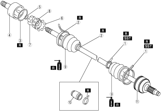
FRONT DRIVE SHAFT DISASSEMBLY/ASSEMBLY [DOUBLE OFFSET JOINT]
id0313008004h5
1. Disassemble in the order indicated in the table.
2. Assemble in the reverse order of disassembly.
acxaaw00000788
|
|
1
|
Boot band (wheel side)
|
|
2
|
Boot band (transaxle side)
|
|
3
|
Clip
(See Clip Disassembly Note.)
|
|
4
|
Outer ring
|
|
5
|
Snap ring
(See Snap Ring Disassembly Note.)
|
|
6
|
Balls
|
|
7
|
Inner Ring
|
|
8
|
Cage
|
|
9
|
Boot
(See Boot Assembly Note.)
(See Boot Disassembly Note.)
|
|
10
|
Dynamic damper
(See Dynamic Damper Assembly Note.)
|
|
11
|
Shaft and ball joint component
|
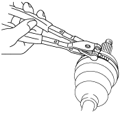
Boot Band (Wheel Side) Disassembly Note
1. Remove the boot clamp with end clamp pliers as shown and discard the clamp.
acxaaw00000429
|
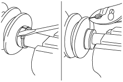
Boot Band (Transaxle Side) Disassembly Note
1. Pry up the locking clips using a screwdriver.
acxaaw00000430
|
2. Pull back the end of the band.
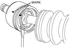
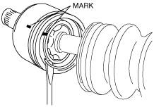
Clip Disassembly Note
1. Mark the drive shaft and outer ring for proper assembly.
acxaaw00000782
|
2. Remove the clip.
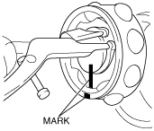
Snap Ring Disassembly Note
1. Mark the drive shaft end, inner ring and cage for proper reassembly.
acxaaw00000783
|
2. Remove the snap ring using snap‐ring pliers.
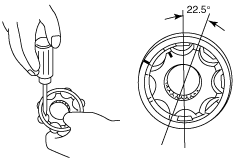
Balls, Inner Ring, Cage Disassembly Note
1. Turn the cage approx. 22.5°and pull the cage and balls from the inner ring.
acxaaw00000784
|
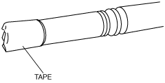
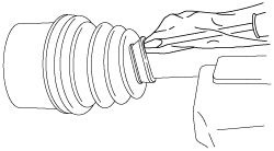
Boot Disassembly Note
1. Wrap the shaft splines with tape.
acxaaw00000434
|
2. Remove the boot.
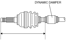
Dynamic Damper Assembly Note
1. Install the dynamic damper as shown in the figure.
acxaaw00000785
|
2. Install the new boot band onto the dynamic damper.
Boot Assembly Note
1. Fill the boot (wheel side) with the specified grease.
2. With the splines of the shaft still wrapped in tape from disassembly, install the boot.
3. Remove the tape.
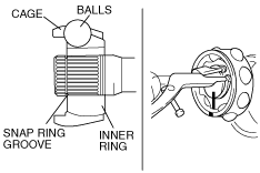
Cage, Inner Ring, Balls, Snap Ring Assembly Note
1. Align the marks and install the balls and cage to the inner ring in the direction shown in the figure.
acxaaw00000786
|
2. Install a new snap ring.
Outer Ring, Clip Assembly Note
1. Fill the outer ring and boot (differential side) with the specified grease.
2. Align the marks, and install the outer ring on to the shaft.
acxaaw00000451
|
3. Install a new clip to the outer ring clip groove.
4. Install the boot.
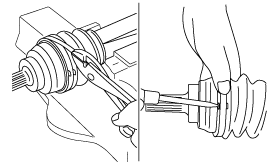
5. Release any trapped air from the boots by carefully lifting up the small end of each boot with a cloth wrapped screwdriver.
acxaaw00000455
|
6. Set the drive shaft to the standard length.
7. Verify that the drive shaft length is within the standard.
Boot Band (Transaxle Side) Assembly Note
1. Fold the band in the direction opposite to the forward revolving direction of the drive shaft and use pliers to pull it tight.
acxaaw00000437
|
2. Lock the end of the band by bending the locking clips.
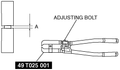
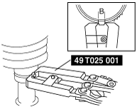
Boot Band (Wheel Side) Assembly Note
1. Adjust clearance A by turning the adjusting bolt of the SST.
acxaaw00000438
|
2. Crimp the wheel side small boot band using the SST. Verify that clearance B is within the specification.
acxaaw00000439
|
3. Verify that the boot band does not protrude from the boot band installation area.
4. Fill the boot with the repair kit grease.
5. Adjust clearance A by turning the adjusting bolt of the SST.
6. Crimp the wheel side big boot band using the SST.
7. Verify that clearance B is within the specification.
8. Verify that the boot band does not protrude from the boot band installation area.