 |
acxaaw00000219
CONTROL VALVE BODY REMOVAL/INSTALLATION [AW6A-EL, AW6AX-EL]
id051723801800
On-Vehicle Removal
1. Disconnect the negative battery cable.
2. Remove the air cleaner component. (See INTAKE-AIR SYSTEM REMOVAL/INSTALLATION [L3 Turbo].)
3. Remove the under cover.
4. Drain the ATF. (See AUTOMATIC TRANSAXLE FLUID (ATF) REPLACEMENT [AW6A-EL, AW6AX-EL].)
5. Remove the resonance chamber. (See INTAKE-AIR SYSTEM REMOVAL/INSTALLATION [L3 Turbo].)
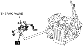
6. Remove the thermo valve. (See OIL COOLER REMOVAL/INSTALLATION [AW6A-EL, AW6AX-EL].)
acxaaw00000219
|
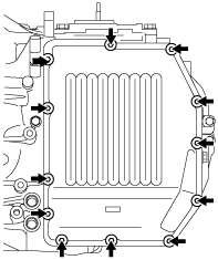
7. Remove the control valve body cover installation bolt.
acxaaw00000220
|
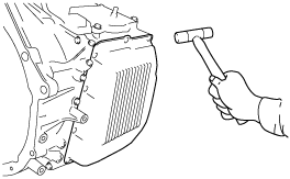
8. Using a plastic hammer, tap the control valve body cover to remove it.
acxaaw00000221
|
acxaaw00000222
|
acxaaw00000223
|
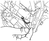
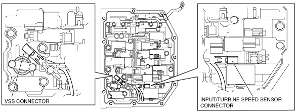
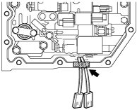
9. Disconnect the solenoid connectors, VSS connector and the input/turbine speed sensor connector.
acxaaw00000224
|
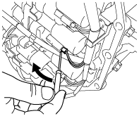
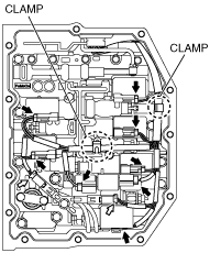
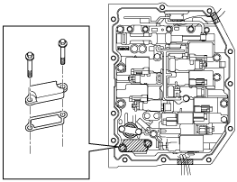
10. Disconnect the coupler component from the clamp.
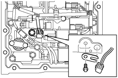
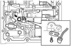
11. Remove the lock plate, and pull out the TFT sensor from the control valve body.
acxaaw00000225
|
12. Remove the O-ring from the TFT sensor.
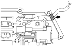
13. Fix the coupler component with tape to the transaxle case as shown in the figure.
acxaaw00000226
|
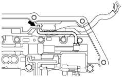
14. Remove the VSS connector and input/turbine speed sensor connector from the solenoid clamp.
acxaaw00000227
|
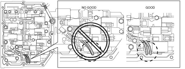
15. Fix the VSS wiring harness and input/turbine speed sensor wiring harness with tape to the transaxle case as shown in the figure.
acxaaw00000228
|
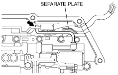
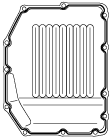
16. Remove the suction cover and the gasket.
acxaaw00000229
|
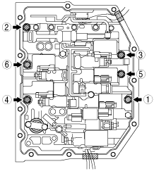
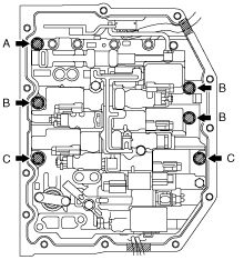
17. Remove the control valve body installation bolts.
acxaaw00000230
|
18. Disconnect the manual valve link and remove the control valve body component.
acxaaw00000231
|
On-Vehicle Installation
1. Connect the manual valve link and install the control valve body component.
acxaaw00000232
|
2. Temporarily install the control valve body component with the bolts.
acxaaw00000233
|
3. Temporarily install the suction cover and a new gasket with the bolts.
acxaaw00000229
|
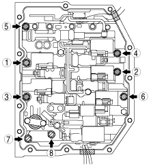
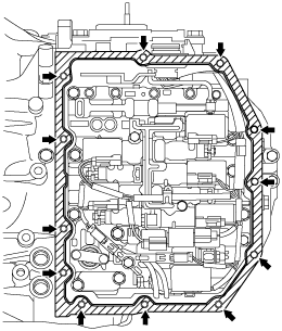
4. Tighten the bolts in the order shown in the figure.
acxaaw00000234
|
5. Install the connector of the VSS and input/turbine speed sensor to the solenoid clamp.
acxaaw00000227
|
acxaaw00000235
|
6. Apply ATF to a new O-ring and install it on the TFT sensor.
7. Install the TFT sensor with the lock plate and a bolt to the control valve body component as shown in the figure.
acxaaw00000236
|
8. Connect the solenoid connectors, VSS connector and the input/turbine speed sensor connector.
9. Connect the coupler component to the clamps.
acxaaw00000224
|
10. Clean sealant and oil off the contact surface of the transaxle case with the control valve body cover and the bolt holes.
acxaaw00000237
|
11. Clean oil off the contact surface of the new control valve body cover with the transaxle case.
12. Apply sealant to the new control valve body cover as shown in the figure.
acxaaw00000238
|
13. Install the new control valve body cover with new seal bolts.
acxaaw00000220
|
14. Install the thermo valve. (See OIL COOLER REMOVAL/INSTALLATION [AW6A-EL, AW6AX-EL].)
15. Install the resonance chamber. (See INTAKE-AIR SYSTEM REMOVAL/INSTALLATION [L3 Turbo].)
16. Install the TCM. (See TCM REMOVAL/INSTALLATION [AW6A-EL, AW6AX-EL].)
17. Add ATF to the specified level. (See AUTOMATIC TRANSAXLE FLUID (ATF) REPLACEMENT [AW6A-EL, AW6AX-EL].)
18. Install the under cover.
19. Install the air cleaner component. (See INTAKE-AIR SYSTEM REMOVAL/INSTALLATION [L3 Turbo].)
20. Connect the negative battery cable.
21. Perform the mechanical system test. (See MECHANICAL SYSTEM TEST [AW6A-EL, AW6AX-EL].)