 |
acxwzw00001808
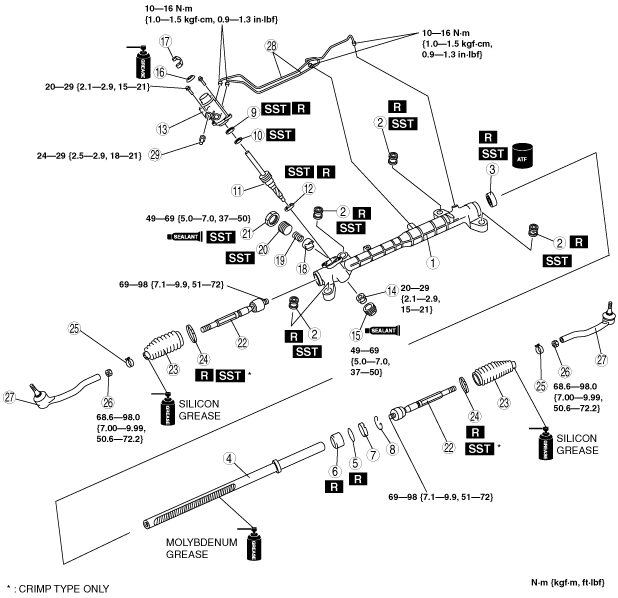
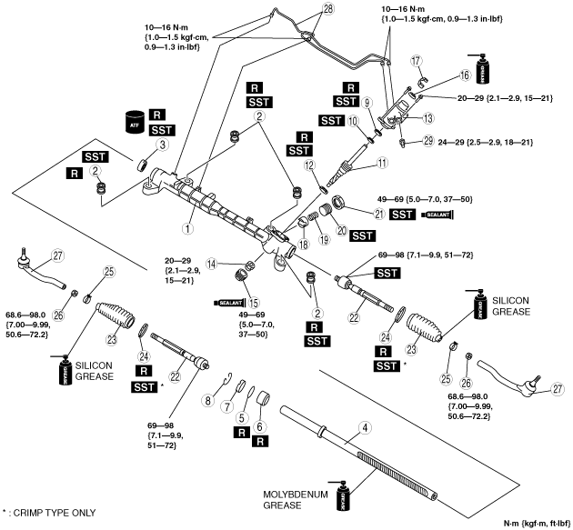
STEERING GEAR AND LINKAGE ASSEMBLY
id061400801200
1. Assemble in the order indicated in the table.
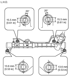
L.H.D.
acxwzw00001808
|
|
1
|
Gear housing
|
|
2
|
Mounting rubber
|
|
3
|
Oil seal
(See Oil Seal Assembly Note.)
|
|
4
|
Steering rack
(See Steering Rack Assembly Note.)
|
|
5
|
O-ring
|
|
6
|
Rack bushing
|
|
7
|
Stopper
(See Stopper Assembly Note.)
|
|
8
|
Clip
|
|
9
|
Oil seal (upper side)
|
|
10
|
Bearing (upper side)
|
|
11
|
Pinion shaft
(See Pinion Shaft Assembly Note.)
|
|
12
|
Oil seal (lower side)
|
|
13
|
Valve housing component
|
|
14
|
Locknut (pinion shaft side)
|
|
15
|
Housing cover
(See Housing Cover Assembly Note.)
|
|
16
|
Dust cover
(See Dust Cover Assembly Note .)
|
|
17
|
Clip
|
|
18
|
Support yoke
|
|
19
|
Yoke spring
|
|
20
|
Adjusting cover
|
|
21
|
Locknut (adjusting cover)
|
|
22
|
Tie rod
(See Tie rod Assembly Note.)
|
|
23
|
Boot
(See Boot Assembly Note.)
|
|
24
|
Boot band
|
|
25
|
Boot clamp
|
|
26
|
Locknut
|
|
27
|
Tie-rod end
|
|
28
|
Oil pipe
|
|
29
|
Return pipe
|
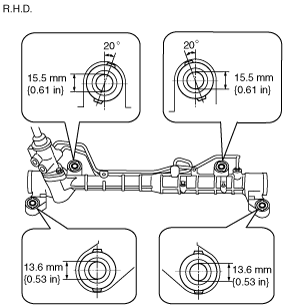
R.H.D.
acxwzw00001809
|
|
1
|
Gear housing
|
|
2
|
Mounting rubber
|
|
3
|
Oil seal
(See Oil Seal Assembly Note.)
|
|
4
|
Steering rack
(See Steering Rack Assembly Note.)
|
|
5
|
O-ring
|
|
6
|
Rack bushing
|
|
7
|
Stopper
(See Stopper Assembly Note.)
|
|
8
|
Clip
|
|
9
|
Oil seal (upper side)
|
|
10
|
Bearing (upper side)
|
|
11
|
Pinion shaft
(See Pinion Shaft Assembly Note.)
|
|
12
|
Oil seal (lower side)
|
|
13
|
Valve housing component
|
|
14
|
Locknut (pinion shaft side)
|
|
15
|
Housing cover
(See Housing Cover Assembly Note.)
|
|
16
|
Dust cover
(See Dust Cover Assembly Note .)
|
|
17
|
Clip
|
|
18
|
Support yoke
|
|
19
|
Yoke spring
|
|
20
|
Adjusting cover
|
|
21
|
Locknut (adjusting cover)
|
|
22
|
Tie rod
(See Tie rod Assembly Note.)
|
|
23
|
Boot
(See Boot Assembly Note.)
|
|
24
|
Boot band
|
|
25
|
Boot clamp
|
|
26
|
Locknut
|
|
27
|
Tie-rod end
|
|
28
|
Oil pipe
|
|
29
|
Return pipe
|
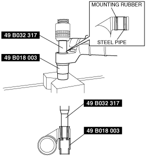
Mounting Rubber Assembly Note
1. Apply soapy water to the rubber part of the mounting rubber.
2. Temporarily install the mounting rubber to the steering gear so that the mounting rubber are in the positions shown in the figure.
acxaaw00001238
|
acxaaw00000374
|
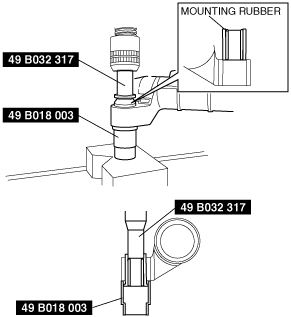
3. Press the mounting rubber until the mounting rubber end comes out completely from the gear housing using the SSTs and a press.
acxaaw00000375
|
4. Reverse the gear housing, then press the mounting rubber until the mounting rubber end comes out completely from the other side. At this time, make sure that the mounting rubber and steel pipe are aligned.
acxaaw00000376
|
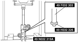
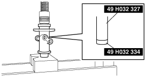
Oil Seal Assembly Note
1. Apply ATF to the lip of a new oil seal.
2. Install the SST (49 N032 319A) to the gear housing with the raised part facing up as shown in the figure.
3. Set the stopper into the gear housing to hold the SSTs as shown in the figure.
acxuuw00000998
|
4. Install the oil seal using the SSTs (49 F032 303, 49 H032 326) and a press.
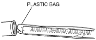
Steering Rack Assembly Note
1. Apply multipurpose grease to the rack teeth.
2. Install a plastic bag to the rack teeth and insert the steering rack in the gear housing.
acxuuw00000999
|
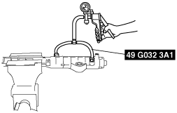
Stopper Assembly Note
1. Using an appropriate pipe and a hammer, insert the rack stopper into the gear housing until the clip installation groove of the gear housing comes out.
acxuuw00001000
|
2. Apply 53.3 kPa {400 mmHg, 15.8 inHg} vacuum with a vacuum pump and verify that it is held for 30 s.
acxuuw00001001
|
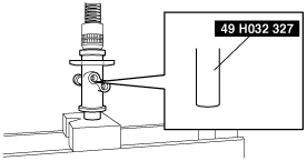
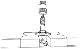
Oil Seal (upper side) Assembly Note
1. Assemble the oil seal (upper side) using the SST.
acxuuw00001002
|
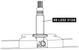
Bearing (upper side) Assembly Note
1. Assemble the bearing (upper side) using the SST.
acxuuw00001003
|
Oil Seal (lower side) Assembly Note
1. Assemble the oil seal (lower side) using the SST.
acxuuw00001007
|
Pinion Shaft Assembly Note
1. Assemble the pinion shaft using a press.
acxuuw00001006
|
Housing Cover Assembly Note
1. Apply silicone sealant to the threads of the housing cover.
2. Assemble the housing cover.
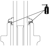
Dust Cover Assembly Note
1. Apply grease to the oil dust cover shown in the figure.
acxuuw00002261
|
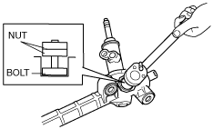
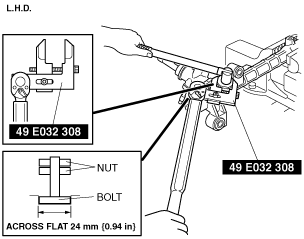
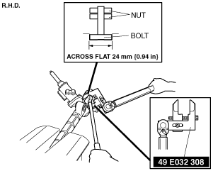
Adjusting Cover, Locknut (Adjusting Cover) Assembly Note
1. Install two nuts to the bolt across a flat 24 mm {0.94 in} and tighten them using a wrench.
acxaaw00000377
|
2. Using the bolt/nut produced in Step 1, install the adjusting cover.
acxaaw00000378
|
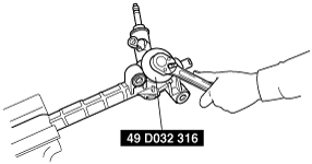
3. Apply sealant to the locknut.
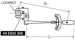
4. Combine the the SST with the torque wrench, then measure A and L as shown in the figure.
acxaaw00001669
|
5. Recalculate the torque by using torque formulas, then secure the adjusting cover with the bolt and nuts created in Step 1, and tighten the locknut using the SST.
acxaaw00001239
|
acxaaw00000379
|
Torque formula
|
Torque unit |
Formula |
|---|---|
|
N·m
|
N·m×[L/A]
|
|
kgf·m
|
kgf·m×[L/A]
|
|
ft·lbf
|
ft·lbf×[L/A]
|
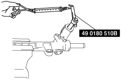
6. Measure the pinion torque using the SST and pull scale.
acxaaw00000380
|
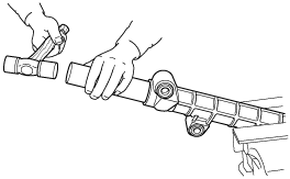
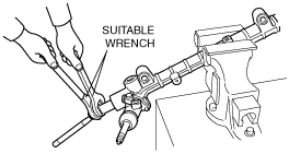
Tie rod Assembly Note
1. Lock the steering rack end against rotation with a suitable wrench and install the tie rod.
acxaaw00000494
|
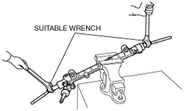
2. Lock the steering rack end against rotation with a suitable wrench and install the other side tie rod.
acxaaw00000495
|
Boot Assembly Note
1. Apply silicone grease to the rubber lip groove.
2. Assemble the boot.
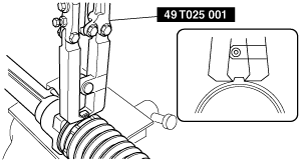
Boot Band (Crimp Type) Assembly Note
1. Assemble the boot band to the boot.
2. Crimp the boot band using the SST.
acxwzw00001805
|
3. Rotate the boot by hand and verify that it is securely installed to the boot band.