 |
acxaaw00000950
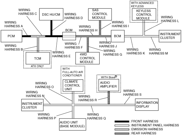
PROCEDURES FOR DETERMINING THE LOCATION OF A MALFUNCTION [MULTIPLEX COMMUNICATION SYSTEM]
id0902e6830500
System Wiring Diagram
acxaaw00000950
|
PCM
1. Inspect the display of DTC U0101 (ATX only), U0121 and/or U0155, using the M-MDS.
(See DTC TABLE [MULTIPLEX COMMUNICATION SYSTEM].)
2. Referring to the following table, determine the malfunctioning part of the CAN system.
|
Module |
Communication status |
Malfunction location |
||
|---|---|---|---|---|
|
TCM (ATX only) |
DSC HU/CM |
Instrument cluster |
||
|
PCM
|
—
|
—
|
—
|
• Wiring harness A
• PCM
|
|
—
|
×
|
×
|
• Wiring harness B
• TCM (ATX only)
|
|
|
×
|
—
|
×
|
• Wiring harness D
• DSC HU/CM
|
|
|
×
|
—
|
—
|
• Wiring harness C
|
|
|
×
|
×
|
—
|
• Wiring harness E
• BCM
• Wiring harness F
• Wiring harness H
• Wiring harness J
• Wiring harness K
• Wiring harness M
• Instrument cluster
|
|
TCM (ATX only)
1. Inspect the display of DTC U0100, U0121, U0140 and/or U0415 using the M-MDS. (See DTC TABLE [MULTIPLEX COMMUNICATION SYSTEM].)
2. Referring to the following table, determine the malfunctioning part of the CAN system.
|
Module |
Communication status |
Malfunction location |
||
|---|---|---|---|---|
|
PCM |
DSC HU/CM |
Instrument cluster |
||
|
TCM (ATX only)
|
—
|
—
|
—
|
• Wiring harness B
• TCM (ATX only)
|
|
—
|
×
|
×
|
• Wiring harness A
• PCM
|
|
|
×
|
—
|
×
|
• Wiring harness D
• DSC HU/CM
|
|
|
×
|
—
|
—
|
• Wiring harness C
|
|
|
×
|
×
|
—
|
• Wiring harness E
• BCM
• Wiring harness F
• Wiring harness H
• Wiring harness J
• Wiring harness K
• Wiring harness M
• Instrument cluster
|
|
DSC HU/CM
1. Inspect the display of DTC U0100, U0101 (ATX only), U0114, U0140 (MTX only), U1900 and/or U2023 using the M-MDS. (See DTC TABLE [MULTIPLEX COMMUNICATION SYSTEM].)
2. Referring to the following table, determine the malfunctioning part of the CAN system.
|
Module |
Communication status |
Malfunction location |
|||
|---|---|---|---|---|---|
|
PCM |
TCM (ATX only) |
4WD control module |
BCM |
||
|
DSC HU/CM
|
—
|
—
|
—
|
—
|
• Wiring harness D
• DSC HU/CM
|
|
—
|
×
|
×
|
×
|
• Wiring harness A
• PCM
|
|
|
×
|
—
|
×
|
×
|
• Wiring harness B
• TCM (ATX only)
|
|
|
—
|
—
|
×
|
×
|
• Wiring harness C
|
|
|
×
|
×
|
—
|
×
|
• Wiring harness G
• 4WD control module
|
|
|
×
|
×
|
—
|
—
|
• Wiring harness E
• BCM
• Wiring harness F
|
|
|
×
|
×
|
×
|
—
|
• Wiring harness H
• Wiring harness J
• BCM
|
|
4WD Control Module
1. Inspect the display of DTC U0100, U0101 (ATX only), U0121, U0140 (MTX only) and/or U0155 using the M-MDS. (See DTC TABLE [MULTIPLEX COMMUNICATION SYSTEM].)
2. Referring to the following table, determine the malfunctioning part of the CAN system.
|
Module |
Communication status |
Malfunction location |
||||
|---|---|---|---|---|---|---|
|
PCM |
TCM (ATX only) |
DSC HU/CM |
BCM |
Instrument cluster |
||
|
4WD Control Module
|
—
|
—
|
—
|
—
|
—
|
• Wiring harness G
• 4WD Control Module
• BCM
|
|
—
|
×
|
×
|
×
|
×
|
• Wiring harness A
• PCM
|
|
|
×
|
—
|
×
|
×
|
×
|
• Wiring harness B
• TCM (ATX only)
|
|
|
—
|
—
|
×
|
×
|
×
|
• Wiring harness C
|
|
|
×
|
×
|
—
|
×
|
×
|
• Wiring harness D
• DSC HU/CM
|
|
|
—
|
—
|
—
|
×
|
×
|
• Wiring harness E
• Wiring harness F
|
|
|
×
|
×
|
×
|
×
|
—
|
• Wiring harness K
• Wiring harness M
• Instrument cluster
|
|
BCM
1. Inspect the display of DTC U0028 and/or U0100 using the M-MDS.
(See DTC TABLE [MULTIPLEX COMMUNICATION SYSTEM].)
2. Referring to the following table, determine the malfunctioning part of the CAN system.
|
Module |
Communication status |
Malfunction location |
|||
|---|---|---|---|---|---|
|
PCM |
DSC HU/CM |
Keyless Control Module (with advanced keyless) |
Instrument cluster |
||
|
BCM
|
—
|
—
|
—
|
—
|
• BCM
|
|
—
|
×
|
×
|
×
|
• Wiring harness A
• Wiring harness C
• PCM
|
|
|
×
|
—
|
×
|
×
|
• Wiring harness D
• DSC HU/CM
|
|
|
—
|
—
|
×
|
×
|
• Wiring harness E
• Wiring harness F
• Wiring harness H
• Wiring harness J
|
|
|
×
|
×
|
—
|
×
|
• Wiring harness L
• Keyless Control Module (with advanced keyless)
|
|
|
×
|
×
|
×
|
—
|
• Wiring harness M
• Instrument cluster
|
|
SAS Control Module
1. Inspect the display of DTC U0155 using the M-MDS.
(See DTC TABLE [MULTIPLEX COMMUNICATION SYSTEM].)
2. Referring to the following table, determine the malfunctioning part of the CAN system.
|
Module |
Communication status |
Malfunction location |
|---|---|---|
|
Instrument cluster |
||
|
SAS control module
|
—
|
• SAS control module
• Wiring harness I
• Wiring harness J
• BCM
• Wiring harness K
• Wiring harness M
• Instrument cluster
|
Keyless Control Module (with advanced keyless)
1. Inspect the display of DTC U0100, U0140, U0323 and/or U2023 using the M-MDS.
(See DTC TABLE [MULTIPLEX COMMUNICATION SYSTEM].)
2. Referring to the following table, determine the malfunctioning part of the CAN system.
|
Module |
Communication status |
Malfunction location |
||
|---|---|---|---|---|
|
PCM |
BCM |
Instrument cluster |
||
|
Keyless Control Module (with advanced keyless)
|
—
|
—
|
—
|
• Wiring harness L
• Keyless Control Module (with advanced keyless)
|
|
—
|
×
|
×
|
• Wiring harness A
• Wiring harness C
• Wiring harness E
• BCM
• Wiring harness F
• Wiring harness H
• Wiring harness J
• PCM
|
|
|
—
|
—
|
×
|
• Wiring harness K
• BCM
|
|
|
×
|
—
|
×
|
• BCM
|
|
|
×
|
×
|
—
|
• Wiring harness M
• Instrument cluster
|
|
Instrument Cluster
1. Inspect the display of DTC U0100, U0101 (ATX only), U0114, U0121, U0140, U0151 U0214 and/or U2023 using the M-MDS. (See DTC TABLE [MULTIPLEX COMMUNICATION SYSTEM].)
2. Referring to the following table, determine the malfunctioning part of the CAN system.
|
Module |
Communication status |
Malfunction location |
||||||
|---|---|---|---|---|---|---|---|---|
|
PCM |
TCM (ATX only) |
DSC HU/CM |
4WD control module |
SAS control module |
BCM |
Keyless Control Module (with advanced keyless) |
||
|
Instrument cluster
|
—
|
—
|
—
|
—
|
—
|
—
|
—
|
• Wiring harness M
• Instrument cluster
|
|
—
|
×
|
×
|
×
|
×
|
×
|
×
|
• Wiring harness A
• PCM
|
|
|
—
|
—
|
×
|
×
|
×
|
×
|
×
|
• Wiring harness C
|
|
|
×
|
—
|
×
|
×
|
×
|
×
|
×
|
• Wiring harness B
• TCM (ATX only)
|
|
|
—
|
—
|
—
|
×
|
×
|
×
|
×
|
• Wiring harness E
• BCM
• Wiring harness F
|
|
|
×
|
×
|
—
|
×
|
×
|
×
|
×
|
• Wiring harness D
• DSC HU/CM
|
|
|
—
|
—
|
—
|
—
|
×
|
×
|
×
|
• Wiring harness H
|
|
|
×
|
×
|
×
|
—
|
×
|
×
|
×
|
• Wiring harness G
• 4WD control module
|
|
|
—
|
—
|
—
|
—
|
—
|
×
|
×
|
• Wiring harness J
• BCM
|
|
|
×
|
×
|
×
|
×
|
—
|
×
|
×
|
• Wiring harness I
• SAS control module
|
|
|
—
|
—
|
—
|
—
|
—
|
—
|
×
|
• Wiring harness K
• BCM
|
|
|
×
|
×
|
×
|
×
|
×
|
—
|
×
|
• BCM
|
|
|
×
|
×
|
×
|
×
|
×
|
×
|
—
|
• Wiring harness L
• Keyless Control Module (with advanced keyless)
|
|
3. Inspect the display of DTC U0164 (with full-auto air conditioner) using the M-MDS. (See DTC TABLE [MULTIPLEX COMMUNICATION SYSTEM].)
4. Referring to the following table, determine the malfunctioning part of the CAN system.
|
Module |
Communication status |
Malfunction location |
|
|---|---|---|---|
|
Climate control unit (with full-auto air conditioner) |
Information display |
||
|
Instrument cluster
|
—
|
—
|
• Wiring harness N
• Instrument cluster
|
|
—
|
×
|
• Wiring harness O
• Climate control unit (with full-auto air conditioner)
|
|
|
×
|
—
|
• Wiring harness Q
• Wiring harness S
• Information display
|
|
Climate control unit (with full-auto air conditioner)
1. Inspect the display of DTC U0155 using the M-MDS. (See DTC TABLE [MULTIPLEX COMMUNICATION SYSTEM].)
2. Referring to the following table, determine the malfunctioning part of the CAN system.
|
Module |
Communication status |
Malfunction location |
|
|---|---|---|---|
|
Instrument cluster |
Information display |
||
|
Climate control unit (with full-auto air conditioner)
|
—
|
—
|
• Wiring harness O
• Climate control unit (with full-auto air conditioner)
|
|
—
|
×
|
• Wiring harness N
• Instrument cluster
|
|
|
×
|
—
|
• Wiring harness Q
• Wiring harness S
• Information display
|
|
Audio Unit (Base Module)
1. Referring to the following table, determine the malfunctioning part of the CAN system.
|
Module |
Communication status |
Malfunction location |
|---|---|---|
|
Information display |
||
|
Audio unit (base module)
|
—
|
• Wiring harness P
• Wiring harness Q
• Wiring harness S
• Audio unit (base module)
• Information display
|
Information display
1. Inspect the display of DTC U0166, U0181 and/or U0184 using the input/output check mode. (See INFORMATION DISPLAY INPUT/OUTPUT CHECK MODE.)
2. Referring to the following table, determine the malfunctioning part of the CAN system.
|
Module |
Communication status |
Malfunction location |
||
|---|---|---|---|---|
|
Climate control unit (with full-auto air conditioner) |
Audio unit (base module) |
Instrument cluster |
||
|
Information display
|
—
|
—
|
—
|
• Wiring harness Q
• Wiring harness S
• Information display
|
|
—
|
×
|
×
|
• Wiring harness O
• Climate control unit (with full-auto air conditioner)
|
|
|
×
|
—
|
×
|
• Wiring harness P
• Car-navigation unit
• Audio unit (base module)
|
|
|
×
|
×
|
—
|
• Wiring harness N
• Instrument cluster
|
|
Repair Procedure
1. Inspect the connector of malfunctioning module.
2. Inspect the malfunctioning wiring harnesses as follow:
3. Make sure to reconnect all disconnected connectors.
4. Clear the CAN system related DTCs using the M-MDS.
5. Verify if the CAN system related DTCs are displayed using the M-MDS.