 |
acxuun00000488
ON-BOARD DIAGNOSTIC OPERATION
id092200103400
Malfunction Detection Function
DTC table
|
DTC |
Malfunction location |
Freeze frame data |
|---|---|---|
|
B1202
|
Fuel gauge sender unit circuit malfunction (open circuit)
|
—
|
|
B1204
|
Fuel gauge sender unit circuit malfunction (short to ground)
|
—
|
|
B1213
|
Only one key ID number is registered.
|
—
|
|
B1342
|
Instrument cluster malfunction
|
—
|
|
B1600
|
The key ID number data cannot be read.
|
—
|
|
B1601
|
The instrument cluster has detected unregistered key ID number.
|
—
|
|
B1602
|
The instrument cluster cannot read key ID number data normally.
|
—
|
|
B1681
|
No detected communication with the coil
|
—
|
|
B2103
|
• Coil antenna malfunction
• The PCM determined a malfunction in the coil antenna even though it is normal.
|
—
|
|
B2139
|
ID number data in the PCM and the instrument cluster do not match.
|
—
|
|
B2141
|
Communication error between the instrument cluster and the PCM (data transfer error)
|
—
|
|
B2431
|
Key ID number registration error
|
—
|
|
B2477
|
Configuration error
|
—
|
|
U0073
|
CAN system communication error (HS-CAN)
|
—
|
|
U0100
|
Communication error to PCM
|
—
|
|
U0101
|
Communication error to TCM
|
—
|
|
U0114
|
Communication error to 4WD control module
|
—
|
|
U0121
|
Communication error to DSC/RSC HU/CM
|
—
|
|
U0140
|
Communication error to BCM
|
—
|
|
U0151
|
Communication error to SAS control module
|
—
|
|
U0164
|
Communication error to climate control unit
|
—
|
|
U0214
|
Communication error to keyless control module
|
—
|
|
U2023
|
Abnormal message from other module
|
×
|
|
U2064
|
Warning light illumination request signal from other modules
|
×
|
|
U2510
|
Communication error between the instrument cluster and the PCM (no response)
|
—
|
|
U2516
|
CAN system communication error (MS-CAN)
|
—
|
Freeze Frame Data
|
Freeze frame data |
Unit |
Note |
|---|---|---|
|
Malfunction type
|
—
|
• Abnormal messages from the PCM
• Warning light illumination request signal from other units
|
|
Illuminated warning light
|
—
|
Target warning light:
• Air bag system warning light
• Generator warning light
• MIL
• Oil pressure warning light
• ABS warning light
• Brake system warning light
• AT warning light
• Keyless warning light
• 4WD warning light
• DSC indicator light
|
|
Meter, gauge control status
|
—
|
Target meter, gauge:
• Speedometer
• Tachometer
• Water temperature gauge
|
|
Traveled distance after DTC recorded
|
km
|
Only the last four digits are recorded
|
|
DTC cleared flag
|
Cleared/Not cleared
|
The freeze frame data will not be cleared even if the DTC data is cleared. If a DTC is cleared, a DTC cleared flag 'Cleared' is recorded with the corresponding freeze frame data.
|
DTCs and recorded freeze frame data
Warning light illumination request signal from other modules (U2064)
|
Freeze frame data |
Warning light illumination request unit |
||||||
|---|---|---|---|---|---|---|---|
|
PCM |
TCM |
DSC HU/CM |
Keyless control module |
4WD control module |
SAS control module |
||
|
Illuminated warning light
|
Air bag system warning light
|
—
|
—
|
—
|
—
|
—
|
×
|
|
Generator warning light
|
×
|
—
|
—
|
—
|
—
|
—
|
|
|
MIL
|
×
|
—
|
—
|
—
|
—
|
—
|
|
|
Oil pressure warning light
|
—
|
—
|
—
|
—
|
—
|
—
|
|
|
DSC indicator light
|
—
|
—
|
—
|
—
|
—
|
—
|
|
|
ABS warning light
|
—
|
—
|
×
|
—
|
—
|
—
|
|
|
Brake system warning light
|
—
|
—
|
×
|
—
|
—
|
—
|
|
|
AT warning light
|
—
|
×
|
—
|
—
|
—
|
—
|
|
|
4WD warning light
|
—
|
—
|
—
|
—
|
×
|
—
|
|
|
Keyless warning light
|
—
|
—
|
—
|
×
|
—
|
—
|
|
|
Meter, gauge control status
|
Speedometer
|
—
|
—
|
—
|
—
|
—
|
—
|
|
Tachometer
|
—
|
—
|
—
|
—
|
—
|
—
|
|
Abnormal messages from other module (U2023)
|
Freeze frame data |
PCM |
|
|---|---|---|
|
Illuminated warning light
|
Air bag system warning light
|
—
|
|
Generator warning light
|
—
|
|
|
MIL
|
×
|
|
|
Oil pressure warning light
|
—
|
|
|
DSC indicator light
|
—
|
|
|
ABS warning light
|
—
|
|
|
Brake system warning light
|
—
|
|
|
AT warning light
|
—
|
|
|
4WD warning light
|
—
|
|
|
Meter, gauge control status
|
Speedometer
|
×
|
|
Tachometer
|
×
|
|
|
Water temperature gauge
|
×
|
|
Input/Output Check Mode
Operation procedure
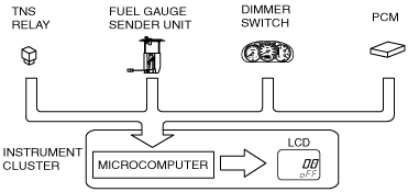
Input circuit check
|
Check code |
Parts sending input signal |
|---|---|
|
08
|
TNS relay
|
|
22
|
Fuel gauge sender unit
|
|
55
|
Dimmer switch
|
|
59
|
Fuel system signal
|
acxuun00000488
|
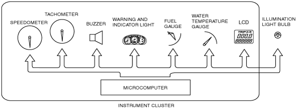
Individual circuit check
|
Check code |
Parts sending input signal |
|---|---|
|
12
|
Speedometer
|
|
13
|
Tachometer
|
|
14
|
Buzzer
|
|
16
|
Fuel-level warning light
|
|
23
|
Fuel gauge
|
|
25
|
Water temperature gauge
|
|
26
|
LCD, warning and indicator light
|
|
57
|
Panel light control
|
acxuun00000489
|
PID/Data Monitor and Record
Monitor item table
|
Monitor item |
Input-output signal/part name |
Unit/State |
Terminal |
|---|---|---|---|
|
IC_DTC_CNT
|
Number of continuous DTCs
|
—
|
—
|
|
IC_ECT
|
Water temperature gauge
|
°C,°F
|
2R, 2T
|
|
IC_NUMKEYS
|
Number of key ID numbers registered with the vehicle
|
—
|
—
|
|
IC_ODO_CNT
|
Odometer rolling count (repeat 0—20 m)
|
m
|
2R, 2T
|
|
IC_SPDMTR
|
Speedometer
|
KPH,MPH
|
|
|
IC_TACHO
|
Tachometer
|
RPM
|