 |
bfw2za00001131
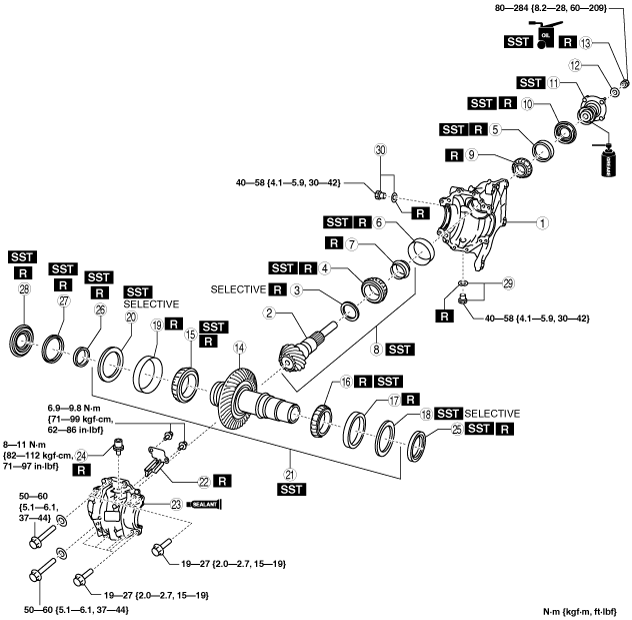
TRANSFER ASSEMBLY [EW6AX-EL]
id0316h2000300
bfw2za00001131
|
|
1
|
Front carrier
|
|
2
|
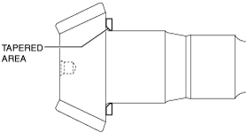
Drive pinion gear
|
|
3
|
Spacer
|
|
4
|
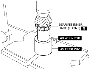
Bearing inner race (front)
|
|
5
|
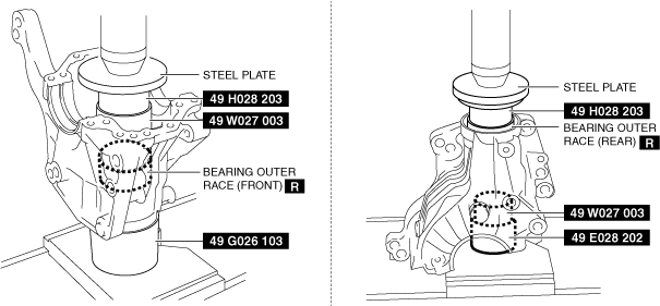
Bearing outer race (rear)
|
|
6
|
Bearing outer race (front)
|
|
7
|
Collapsible spacer
|
|
8
|
Drive pinion gear component
|
|
9
|
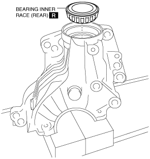
Bearing inner race (rear)
|
|
10
|
Oil seal
|
|
11
|
Companion flange component
|
|
12
|
Washer
|
|
13
|
Locknut
|
|
14
|
Ring gear shaft
|
|
15
|
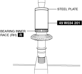
Bearing inner race (RH)
|
|
16
|
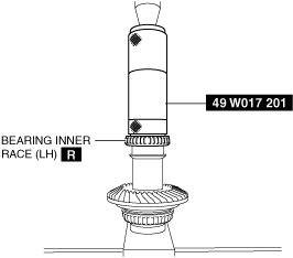
Bearing inner race (LH)
|
|
17
|
Bearing outer race (LH)
|
|
18
|
Adjustment shim (LH)
|
|
19
|
Bearing outer race (RH)
|
|
20
|
Adjustment shim (RH)
|
|
21
|
Ring gear shaft component
|
|
22
|
Baffle plate
|
|
23
|
Drive gear case
|
|
24
|
Breather
|
|
25
|
Transfer oil seal (LH)
|
|
26
|
Transfer oil seal (RH) No.3
|
|
27
|
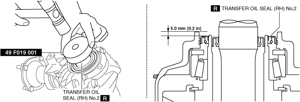
Transfer oil seal (RH) No.2
|
|
28
|
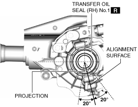
Transfer oil seal (RH) No.1
|
|
29
|
Drain plug, washer
|
|
30
|
Oil level plug, washer
|
1. Clean the contact surfaces of the front carrier and drive gear case.
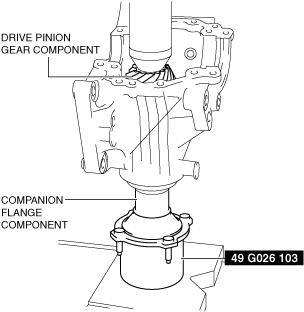
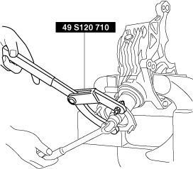
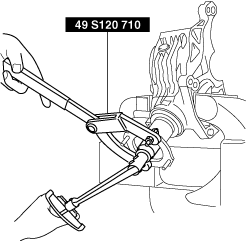
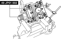
2. Assemble the drive pinion gear component and companion flange to the front carrier using the following procedure.
bfw2za00001132
|
Spacer table
|
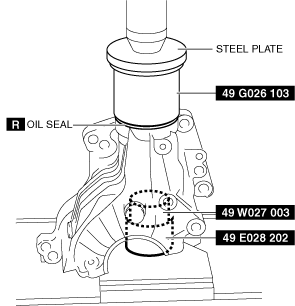
Identification number |
Thickness (mm {in}) |
Identification number |
Thickness (mm {in}) |
|---|---|---|---|
|
08
|
3.080 {0.1213}
|
29
|
3.290 {0.1295}
|
|
09
|
3.095 {0.1219}
|
30
|
3.305 {0.1301}
|
|
11
|
3.110 {0.1224}
|
32
|
3.320 {0.1307}
|
|
12
|
3.125 {0.1230}
|
33
|
3.335 {0.1313}
|
|
14
|
3.140 {0.1236}
|
35
|
3.350 {0.1319}
|
|
15
|
3.155 {0.1242}
|
36
|
3.365 {0.1325}
|
|
17
|
3.170 {0.1248}
|
38
|
3.380 {0.1331}
|
|
18
|
3.185 {0.1254}
|
39
|
3.395 {0.1337}
|
|
20
|
3.200 {0.1260}
|
41
|
3.410 {0.1343}
|
|
21
|
3.215 {0.1266}
|
42
|
3.425 {0.1348}
|
|
23
|
3.230 {0.1272}
|
44
|
3.440 {0.1354}
|
|
24
|
3.245 {0.1278}
|
45
|
3.455 {0.1360}
|
|
26
|
3.260 {0.1283}
|
47
|
3.470 {0.1366}
|
|
27
|
3.275 {0.1289}
|
−
|
−
|
bfw2za00001133
|
bfw2za00001134
|
bfw2za00001135
|
bfw2za00001136
|
bfw3ja00000633
|
bfw3ja00000656
|
bfw2za00001135
|
bfw2za00001137
|
bfw2za00001136
|
bfw3ja00000633
|
bfw3ja00000656
|
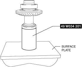
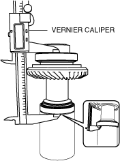
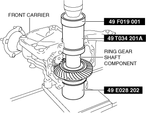
3. Assemble the ring gear shaft component to the front carrier using the following procedure.
bfw2za00001138
|
bfw2za00001139
|
bfw2za00001179
|
bfw2za00001180
|
bfw2za00001142
|
bfw2za00001143
|
Adjustment shim (LH) table
|
Part number |
Thickness (mm {in}) |
Part number |
Thickness (mm {in}) |
|---|---|---|---|
|
CN01 27 3D1
|
2.490 {0.09803}
|
CN01 27 3F1
|
3.030 {0.1193}
|
|
CN01 27 3D2
|
2.520 {0.09921}
|
CN01 27 3F2
|
3.060 {0.1205}
|
|
CN01 27 3D3
|
2.550 {0.1004}
|
CN01 27 3F3
|
3.090 {0.1217}
|
|
CN01 27 3D4
|
2.580 {0.1016}
|
CN01 27 3F4
|
3.120 {0.1228}
|
|
CN01 27 3D5
|
2.610 {0.1028}
|
CN01 27 3F5
|
3.150 {0.1240}
|
|
CN01 27 3D6
|
2.640 {0.1039}
|
CN01 27 3F6
|
3.180 {0.1252}
|
|
CN01 27 3D7
|
2.670 {0.1051}
|
CN01 27 3F7
|
3.210 {0.1264}
|
|
CN01 27 3D8
|
2.700 {0.1063}
|
CN01 27 3F8
|
3.240 {0.1276}
|
|
CN01 27 3D9
|
2.730 {0.1075}
|
CN01 27 3F9
|
3.270 {0.1287}
|
|
CN01 27 3E1
|
2.760 {0.1087}
|
CN01 27 3G1
|
3.300 {0.1299}
|
|
CN01 27 3E2
|
2.790 {0.1098}
|
CN01 27 3G2
|
3.330 {0.1311}
|
|
CN01 27 3E3
|
2.820 {0.1110}
|
CN01 27 3G3
|
3.360 {0.1323}
|
|
CN01 27 3E4
|
2.850 {0.1122}
|
CN01 27 3G4
|
3.390 {0.1335}
|
|
CN01 27 3E5
|
2.880 {0.1134}
|
CN01 27 3G5
|
3.420 {0.1346}
|
|
CN01 27 3E6
|
2.910 {0.1146}
|
CN01 27 3G6
|
3.450 {0.1358}
|
|
CN01 27 3E7
|
2.940 {0.1157}
|
CN01 27 3G7
|
3.480 {0.1370}
|
|
CN01 27 3E8
|
2.970 {0.1169}
|
CN01 27 3G8
|
3.510 {0.1382}
|
|
CN01 27 3E9
|
3.000 {0.1181}
|
−
|
−
|
Adjustment shim (RH) table
|
Part number |
Thickness (mm {in}) |
Part number |
Thickness (mm {in}) |
|---|---|---|---|
|
CN01 27 355
|
2.490 {0.09803}
|
CN01 27 375
|
3.030 {0.1193}
|
|
CN01 27 356
|
2.520 {0.09921}
|
CN01 27 376
|
3.060 {0.1205}
|
|
CN01 27 357
|
2.550 {0.1004}
|
CN01 27 377
|
3.090 {0.1217}
|
|
CN01 27 358
|
2.580 {0.1016}
|
CN01 27 378
|
3.120 {0.1228}
|
|
CN01 27 359
|
2.610 {0.1028}
|
CN01 27 379
|
3.150 {0.1240}
|
|
CN01 27 361
|
2.640 {0.1039}
|
CN01 27 3B1
|
3.180 {0.1252}
|
|
CN01 27 362
|
2.670 {0.1051}
|
CN01 27 3B2
|
3.210 {0.1264}
|
|
CN01 27 363
|
2.700 {0.1063}
|
CN01 27 3B3
|
3.240 {0.1276}
|
|
CN01 27 364
|
2.730 {0.1075}
|
CN01 27 3B4
|
3.270 {0.1287}
|
|
CN01 27 365
|
2.760 {0.1087}
|
CN01 27 3B5
|
3.300 {0.1299}
|
|
CN01 27 366
|
2.790 {0.1098}
|
CN01 27 3B6
|
3.330 {0.1311}
|
|
CN01 27 367
|
2.820 {0.1110}
|
CN01 27 3B7
|
3.360 {0.1323}
|
|
CN01 27 368
|
2.850 {0.1122}
|
CN01 27 3B8
|
3.390 {0.1335}
|
|
CN01 27 369
|
2.880 {0.1134}
|
CN01 27 3B9
|
3.420 {0.1346}
|
|
CN01 27 371
|
2.910 {0.1146}
|
CN01 27 3C1
|
3.450 {0.1358}
|
|
CN01 27 372
|
2.940 {0.1157}
|
CN01 27 3C2
|
3.480 {0.1370}
|
|
CN01 27 373
|
2.970 {0.1169}
|
CN01 27 3C3
|
3.510 {0.1382}
|
|
CN01 27 374
|
3.000 {0.1181}
|
−
|
−
|
bfw2za00001144
|
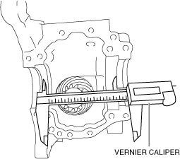
4. Perform the ring gear and drive pinion backlash adjustment.
bfw3ja00000643
|
bfw3ja00000644
|
Adjustment shim (LH) table
|
Part number |
Thickness (mm {in}) |
Part number |
Thickness (mm {in}) |
|---|---|---|---|
|
CN01 27 3D1
|
2.490 {0.09803}
|
CN01 27 3F1
|
3.030 {0.1193}
|
|
CN01 27 3D2
|
2.520 {0.09921}
|
CN01 27 3F2
|
3.060 {0.1205}
|
|
CN01 27 3D3
|
2.550 {0.1004}
|
CN01 27 3F3
|
3.090 {0.1217}
|
|
CN01 27 3D4
|
2.580 {0.1016}
|
CN01 27 3F4
|
3.120 {0.1228}
|
|
CN01 27 3D5
|
2.610 {0.1028}
|
CN01 27 3F5
|
3.150 {0.1240}
|
|
CN01 27 3D6
|
2.640 {0.1039}
|
CN01 27 3F6
|
3.180 {0.1252}
|
|
CN01 27 3D7
|
2.670 {0.1051}
|
CN01 27 3F7
|
3.210 {0.1264}
|
|
CN01 27 3D8
|
2.700 {0.1063}
|
CN01 27 3F8
|
3.240 {0.1276}
|
|
CN01 27 3D9
|
2.730 {0.1075}
|
CN01 27 3F9
|
3.270 {0.1287}
|
|
CN01 27 3E1
|
2.760 {0.1087}
|
CN01 27 3G1
|
3.300 {0.1299}
|
|
CN01 27 3E2
|
2.790 {0.1098}
|
CN01 27 3G2
|
3.330 {0.1311}
|
|
CN01 27 3E3
|
2.820 {0.1110}
|
CN01 27 3G3
|
3.360 {0.1323}
|
|
CN01 27 3E4
|
2.850 {0.1122}
|
CN01 27 3G4
|
3.390 {0.1335}
|
|
CN01 27 3E5
|
2.880 {0.1134}
|
CN01 27 3G5
|
3.420 {0.1346}
|
|
CN01 27 3E6
|
2.910 {0.1146}
|
CN01 27 3G6
|
3.450 {0.1358}
|
|
CN01 27 3E7
|
2.940 {0.1157}
|
CN01 27 3G7
|
3.480 {0.1370}
|
|
CN01 27 3E8
|
2.970 {0.1169}
|
CN01 27 3G8
|
3.510 {0.1382}
|
|
CN01 27 3E9
|
3.000 {0.1181}
|
−
|
−
|
Adjustment shim (RH) table
|
Part number |
Thickness (mm {in}) |
Part number |
Thickness (mm {in}) |
|---|---|---|---|
|
CN01 27 355
|
2.490 {0.09803}
|
CN01 27 375
|
3.030 {0.1193}
|
|
CN01 27 356
|
2.520 {0.09921}
|
CN01 27 376
|
3.060 {0.1205}
|
|
CN01 27 357
|
2.550 {0.1004}
|
CN01 27 377
|
3.090 {0.1217}
|
|
CN01 27 358
|
2.580 {0.1016}
|
CN01 27 378
|
3.120 {0.1228}
|
|
CN01 27 359
|
2.610 {0.1028}
|
CN01 27 379
|
3.150 {0.1240}
|
|
CN01 27 361
|
2.640 {0.1039}
|
CN01 27 3B1
|
3.180 {0.1252}
|
|
CN01 27 362
|
2.670 {0.1051}
|
CN01 27 3B2
|
3.210 {0.1264}
|
|
CN01 27 363
|
2.700 {0.1063}
|
CN01 27 3B3
|
3.240 {0.1276}
|
|
CN01 27 364
|
2.730 {0.1075}
|
CN01 27 3B4
|
3.270 {0.1287}
|
|
CN01 27 365
|
2.760 {0.1087}
|
CN01 27 3B5
|
3.300 {0.1299}
|
|
CN01 27 366
|
2.790 {0.1098}
|
CN01 27 3B6
|
3.330 {0.1311}
|
|
CN01 27 367
|
2.820 {0.1110}
|
CN01 27 3B7
|
3.360 {0.1323}
|
|
CN01 27 368
|
2.850 {0.1122}
|
CN01 27 3B8
|
3.390 {0.1335}
|
|
CN01 27 369
|
2.880 {0.1134}
|
CN01 27 3B9
|
3.420 {0.1346}
|
|
CN01 27 371
|
2.910 {0.1146}
|
CN01 27 3C1
|
3.450 {0.1358}
|
|
CN01 27 372
|
2.940 {0.1157}
|
CN01 27 3C2
|
3.480 {0.1370}
|
|
CN01 27 373
|
2.970 {0.1169}
|
CN01 27 3C3
|
3.510 {0.1382}
|
|
CN01 27 374
|
3.000 {0.1181}
|
−
|
−
|
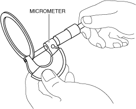
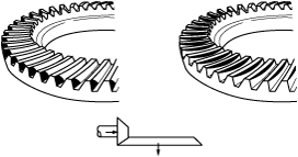
5. Perform the drive pinion gear and ring gear shaft tooth contact inspection using the following procedure.
bfw3ja00000661
|
bfw3ja00000662
|
bfw3ja00000663
|
Spacer table
|
Identification number |
Thickness (mm {in}) |
Identification number |
Thickness (mm {in}) |
|---|---|---|---|
|
08
|
3.080 {0.1213}
|
29
|
3.290 {0.1295}
|
|
09
|
3.095 {0.1219}
|
30
|
3.305 {0.1301}
|
|
11
|
3.110 {0.1224}
|
32
|
3.320 {0.1307}
|
|
12
|
3.125 {0.1230}
|
33
|
3.335 {0.1313}
|
|
14
|
3.140 {0.1236}
|
35
|
3.350 {0.1319}
|
|
15
|
3.155 {0.1242}
|
36
|
3.365 {0.1325}
|
|
17
|
3.170 {0.1248}
|
38
|
3.380 {0.1331}
|
|
18
|
3.185 {0.1254}
|
39
|
3.395 {0.1337}
|
|
20
|
3.200 {0.1260}
|
41
|
3.410 {0.1343}
|
|
21
|
3.215 {0.1266}
|
42
|
3.425 {0.1348}
|
|
23
|
3.230 {0.1272}
|
44
|
3.440 {0.1354}
|
|
24
|
3.245 {0.1278}
|
45
|
3.455 {0.1360}
|
|
26
|
3.260 {0.1283}
|
47
|
3.470 {0.1366}
|
|
27
|
3.275 {0.1289}
|
−
|
−
|
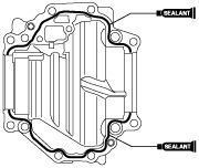
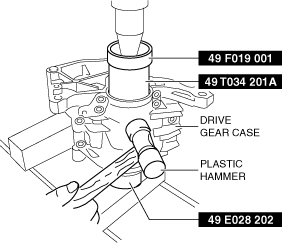
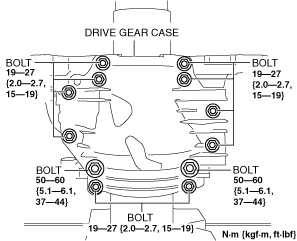
6. Install the drive gear case to the front carrier using the following procedure.
bfw2za00001145
|
bfw2za00001144
|
bfw3ja00000665
|
bfw2za00001146
|
bfw2za00001147
|
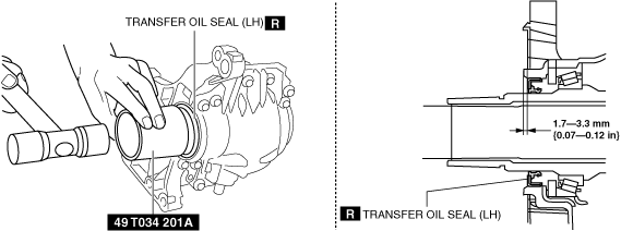
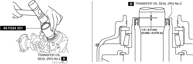
7. Assemble a transfer oil seal using the following procedure.
bfw2za00001148
|
bfw2za00001149
|
bfw2za00001150
|
bfw2za00001151
|
bfw2za00001152
|
8. Assemble a new washer and drain plug.
9. Assemble a new washer and oil level plug.