|
B10A2:00
|
Vehicle collision
|
• Collision signal from SAS control module is received.
|
|
P0016:00
|
Camshaft position/Crankshaft position correlation problem
|
• While the crankshaft rotates 15 times with the following conditions A or B met, the CKP sensor and CMP sensor input signals do not match.
Condition A
-
― Battery positive voltage: 8 V or more
― 0.5 s have elapsed after ignition is switched ON (engine on)
― Engine speed: 1,000 rpm or less
Condition B
-
― Battery positive voltage: 8 V or more
― 0.5 s have elapsed after ignition is switched ON (engine on)
― Engine speed: 700—1,000 rpm
― Engine coolant temperature: -10 °C or more
― The following DTCs are not detected
-
• ECT sensor: P0118:00, P0117:00
• CMP sensor: P0341:00, P0342:00
• CKP sensor: P0336:00, P0337:00
• Constant voltage power supply control system: P0642:00, P0643:00
• Constant voltage power supply control system: P0652:00, P0653:00
|
|
P0031:00
|
A/F sensor heater control circuit low input
|
• With the following conditions met, a condition is detected by the PCM for 5 s in which the voltage while the A/F sensor heater is operating or not operating is the specified value or less.
-
― Battery positive voltage: 10 V or more
― A/F sensor heater control duty value: 90 % or less
|
|
P0032:00
|
A/F sensor heater control circuit high input
|
• With the following conditions met, a condition is detected by the PCM for 5 s in which the voltage while the A/F sensor heater is operating or not operating is the specified value or more.
-
― Battery positive voltage: 10 V or more
― A/F sensor heater control duty value: 10 % or more
|
|
P0034:00
|
Compressor bypass solenoid valve control circuit low input
|
• With the following conditions met, the compressor bypass solenoid valve voltage is less than the specified value for a continuous 5 s when the following conditions are met:
-
― Battery positive voltage: 8—20 V
― 0.5 s have elapsed after ignition is switched ON (engine off or on)
|
|
P0035:00
|
Compressor bypass solenoid valve control circuit high input
|
• When all of the following conditions are met, a condition whereby the compressor bypass solenoid valve control circuit current is the specification or more continues for 5 s.
-
― Battery positive voltage: 8.0—16 V
― 0.5 s have elapsed after ignition is switched ON (engine off or on)
|
|
P0045:00
|
Regulating valve actuator control circuit problem
|
• The regulating valve actuator control duty value is 90% or more for a continuous 3 s.
|
|
P0046:00
|
Regulating valve actuator dc motor control circuit problem
|
• The DC motor drive current of the regulating valve actuator or the temperature of the DC motor drive circuit exceeds the specification for a continuous 2.5 s.
|
|
P004A:00
|
Variable turbine geometry turbocharger actuator control circuit problem
|
• The variable turbine geometry turbocharger actuator control duty value is 90% or more for a continuous 3 s.
|
|
P004B:00
|
Variable turbine geometry turbocharger actuator DC motor control circuit problem
|
• The DC motor drive current of the variable turbine geometry turbocharger actuator or the temperature of the DC motor drive circuit exceeds the specification for a continuous 2.5 s.
|
|
P0072:00
|
Ambient temperature sensor circuit low input
|
• The ambient temperature sensor voltage is less than 0.14 V for a continuous 5 s.
|
|
P0073:00
|
Ambient temperature sensor circuit high input
|
• The ambient temperature sensor voltage exceeds 4.9 V for a continuous 5 s.
|
|
P007B:00
|
Boost air temperature sensor correlation problem
|
• With the following conditions met, the difference between the boost air temperature sensor output value and the IAT sensor No.1 output value is 150 °C or more, or the difference between the boost air temperature sensor output and the IAT sensor No.2 output value is 150 °C or more for a continuous 0.128 s.
-
― Before starting the engine, leave the vehicle with the engine turned off for 6 h or more.
― Battery positive voltage: 10 V or more
― Ignition is switched ON (engine off or on)
― The following DTCs are not detected
-
• Boost air temperature sensor: P007C:00, P007D:00
• IAT sensor No.1: P0112:00, P0113:00
• IAT sensor No.2: P1118:00, P1119:00
• Malfunction in instrument cluster: P2610:00
• ECT sensor: P0118:00, P0117:00
|
|
P007C:00
|
Boost air temperature sensor circuit low input
|
• With the following conditions met, the output voltage of the boost air temperature sensor is less than 0.05 V for a continuous 5 s.
-
― Battery positive voltage: 8—16 V
― 0.5 s have elapsed after the ignition was switched ON (engine off or on)
|
|
P007D:00
|
Boost air temperature sensor circuit high input
|
• With the following conditions met, the output voltage of the boost air temperature sensor exceeds 4.94 V for a continuous 5 s.
-
― Battery positive voltage: 8—16 V
― 0.5 s have elapsed after ignition is switched ON (engine off or on)
|
|
P0087:00
|
Low fuel pressure malfunction in common rail fuel pressure control system
|
• With the following conditions met, the actual fuel pressure is 20 MPa lower than the target fuel pressure for a continuous 5 s.
-
― When the following conditions continue for 5 s
-
• Battery positive voltage: 8.0 V or more
• During fuel pressure control
• Change in target fuel pressure during half-rotation of crankshaft: -9 to 9 MPa
• Fuel temperature: 8.85—70 °C
• Target fuel discharge amount from supply pump: -10,000 mm3/rev
― The following DTCs are not detected
-
• Suction control valve: P0628:00, P0629:00
• Common rail fuel pressure control system: P0089:00
• Fuel pressure relief valve control system: P009B:00, P009C:00, P009D:00
• Constant voltage power supply control system: P0652:00, P0653:00
• Fuel pressure sensor: P01C6:00, P01C5:00, P018D:00, P018C:00, P10CD:00
• Fuel temperature sensor: P10D5:00
• LIN communication system: U1201:00, U1202:00, U1203:00, U1204:00
|
|
P0088:00
|
High fuel pressure malfunction in common rail fuel pressure control system
|
• With the following conditions met, the actual fuel pressure is 20 MPa higher than the target fuel pressure for a continuous 5 s.
-
― The following conditions continue for 5 s
-
• Battery positive voltage: 8.0 V or more
• Fuel pressure control: During execution
• Change in target fuel pressure during half-rotation of crankshaft: -9—9 MPa
• Temperature: 8.85—70 °C
• Target fuel discharge amount from supply pump: -10,000 mm3/rev
― The following DTCs are not detected
-
• Suction control valve: P0628:00, P0629:00
• Common rail fuel pressure control system: P0089:00
• Fuel pressure relief valve control system: P009B:00, P009C:00, P009D:00
• Constant voltage power supply control system: P0652:00, P0653:00
• Fuel pressure sensor: P01C6:00, P01C5:00, P018D:00, P018C:00, P10CD:00
• Fuel temperature sensor: P10D5:00
• LIN communication system: U1201:00, U1202:00, U1203:00, U1204:00
|
|
P0089:00
|
High fuel pressure malfunction in common rail fuel pressure control system
|
• With the following conditions met, the actual fuel pressure exceeds 217 MPa for a continuous 3 s.
-
― Battery positive voltage: 8—16 V
― 0.5 s have elapsed after ignition is switched ON (engine off or on)
― The following DTCs are not detected
-
• Fuel pressure sensor: P01C6:00, P01C5:00, P018D:00, P018C:00, P10CD:00
|
|
P0093:00
|
Fuel leakage from fuel pressure control system
|
• With the following conditions met, a condition in which the amount of fuel leakage exceeds 240 mm3/stroke is detected 3 times.
-
― Battery positive voltage: 8 V or more
― Engine speed: 600 rpm or more
― Fuel-cut control is not implemented
― Fuel pressure relief valve: Closed
― Fuel pressure control: During execution
― CKP sensor: Normal
― The following DTCs are not detected
-
• Suction control valve: P0628:00, P0629:00
• Common rail fuel pressure control system: P0089:00
• Fuel injector: P2146:00, P2149:00, P2148:00, P2151:00, P2147:00, P2150:00, P1379:00, P1378:00, P0201:00, P0202:00, P0203:00, P0204:00
• Malfunction in PCM: P062B:00
• Fuel pressure sensor: P01C6:00, P01C5:00, P018D:00, P018C:00, P10CD:00
|
|
P009B:00
|
Fuel pressure relief valve signal circuit problem
|
• With the following conditions met, the operation amount of the fuel pressure relief valve drive current control switch is the specification or less.
-
― Battery positive voltage: 10—16 V
― During fuel pressure relief valve operation
|
|
P009C:00
|
Fuel pressure relief valve signal circuit low input
|
• When any of the following conditions is met:
-
― With the following conditions met, the operation amount of the fuel pressure relief valve drive current control switch is not within the specification.
-
• Battery positive voltage: 10—16 V
• During fuel pressure relief valve operation
-
― With the following conditions met, the fuel pressure relief valve drive circuit downstream voltage is the specified value or less.
-
• Battery positive voltage: 10—16 V
• Fuel pressure relief valve is stopped (while closed)
|
|
P009D:00
|
Fuel pressure relief valve signal circuit high input
|
• With the following conditions met, the operation amount of the fuel pressure relief valve drive current control switch is the specification or more.
-
― Battery positive voltage: 10—16 V
― During fuel pressure relief valve operation
|
|
P009F:00
|
Fuel pressure relief valve malfunction (stuck close)
|
• When the following conditions are met, the pressure reduction amount during the fuel pressure relief valve operation is insufficient for several seconds continuously.
-
― Battery positive voltage: 10—16 V
― During fuel pressure relief valve operation
― Fuel pump: Fuel not discharged
― Fuel injector: During fuel cut
― Fuel temperature: 8.9 °C or more
― The following DTCs are not detected
-
• Suction control valve: P0628:00, P0629:00
• Fuel pressure control system: P0093:00
• Fuel pressure relief valve control system: P009B:00, P009C:00, P009D:00
• Fuel temperature sensor: P10D5:00
• Fuel pressure sensor: P01C6:00, P01C5:00, P018D:00, P018C:00, P10CD:00
• LIN communication system: U1201:00, U1202:00, U1203:00, U1204:00
|
|
P0101:00
|
MAF sensor circuit range/performance problem
|
• When the following conditions are met, a condition whereby the intake air amount compared to the estimated intake air amount deviates above the specified value continues for 6 s.
-
― 1 s or more elapses after selector lever is operated
― Estimated intake air amount: 0.02―2.0 g/stroke
― BARO sensor: 72 kPa or more
― MAF sensor No.1: 10 °C or more
― ECT sensor: 10 °C or more
― Engine speed: 1,000―3,000 rpm
― During fuel cut
― Intake shutter valve opening angle: 25―95 °
― Compressor bypass solenoid valve actual opening angle: Closed
― Regulating valve target opening angle: Closed
― Variable turbine geometry turbocharger actuator target opening angle: 40 % or lower
― EGR valve position sensor: Within 1 %
― The following DTCs are not detected
-
• MAF sensor: P0102:00, P0103:00
• BARO sensor: P2228:00, P2229:00
• EGR valve position sensor: P0405:00, P0406:00
• EGR valve control system: P0404:00
• EGR cooler bypass valve control system: P245A:00
• ECT sensor: P0117:00, P0118:00
• MAP sensor No.3: P0107:00, P0108:00
• Regulating valve actuator position sensor: P2564:00, P2565:00
• APP sensor No.1: P2122:00, P2123:00
• APP sensor No.2: P2127:00, P2128:00
• APP sensor: P2138:00
• Intake shutter valve position sensor: P0122:00, P0123:00
• IAT sensor No.2: P1118:00, P1119:00
• Exhaust gas pressure sensor No.1: P0472:00, P0473:00
• Exhaust gas temperature sensor No.1: P0545:00, P0546:00
• Regulating valve actuator DC motor control system: P0046:00
• Variable turbine geometry turbocharger actuator position sensor: P2588:00, P2589:00, P004A:00
|
|
P0102:00
|
MAF sensor circuit low input
|
• With the following conditions met, the MAF sensor voltage is less than 0.12 V for a continuous 5 s.
-
― Battery positive voltage: 8—16 V
― 0.5 s have elapsed after ignition is switched ON (engine off or on)
― The following DTCs are not detected
-
• Constant voltage power supply control system: P0642:00, P0643:00
|
|
P0103:00
|
MAF sensor circuit high input
|
• With the following conditions met, the MAF sensor voltage is 4.61 V or more for a continuous 5 s.
-
― Battery positive voltage: 8—16 V
― 0.5 s have elapsed after ignition is switched ON (engine off or on)
― The following DTCs are not detected
-
• Constant voltage power supply control system: P0642:00, P0643:00
|
|
P0105:00
|
MAP sensor No.2/BARO sensor control circuit problem
|
• The PCM detects a condition 4 times in which the difference between the maximum intake air pressure when the following condition A is met and the minimum intake air pressure when the following condition B is met is less than 2.1 kPa.
Condition A
-
― 0.032 s or more have elapsed with all of the following conditions met:
-
• Battery positive voltage: 8 V or more
• 0.5 s have elapsed after ignition is switched ON (engine off or on)
• Engine coolant temperature: 30 °C or more
• Intake air temperature: -10 °C or more
• Barometric pressure: 65—120 kPa
• Change in fuel injection amount: 4 mm3/st or less within 0.032 s
• Vehicle speed: 15 km/h or more
• Target intake air pressure is 150 kPa or more for 1.5 s or more
• Difference in fuel injection amount before and after correction is 5 mm3/st or less
• MAP sensor No.2: P0107:00 and P0108:00 are not detected
Condition B
-
― 1.5 s or more have elapsed with all of the following conditions met:
-
• Battery positive voltage: 8 V or more
• 0.5 s have elapsed after ignition is switched ON (engine on)
• Engine coolant temperature: 30 °C or more
• Intake air temperature: -10 °C or more
• Barometric pressure: 65—120 kPa
• Change in fuel injection amount: 4 mm3/st or less within 0.032 s
• Engine speed: 1,200 rpm or less
• Idle speed control: Being performed
• Fuel injection amount: 25 mm3/st or less
• MAP sensor No.2: P0107:00 and P0108:00 are not detected
• Vehicle speed is 0 km/h or selector lever is in P or N position
|
|
P0106:00
|
MAP sensor No.2 circuit range/performance problem
|
• When either condition A, condition B, or condition C is met with the following conditions met.
-
― Battery positive voltage: 10 V or more
― 7 to 9 s have elapsed after ignition is switched off
― The following DTCs are not detected
-
• Constant voltage power supply control system: P0642:00, P0643:00
• MAP sensor No.1: P0237:00, P0238:00
• MAP sensor No.2: P0107:00, P0108:00
• Exhaust gas pressure sensor: P0472:00, P0473:00
• BARO sensor: P2226:00, P2228:00, P2229:00
Condition A
• Difference between the value detected by MAP sensor No.2 and the barometric pressure exceeds 11.5 kPa.
Condition B
• Difference between the value detected by MAP sensor No.2 and the value detected by exhaust gas pressure No.1 exceeds 60.1 kPa.
Condition C
• Difference between the value detected by MAP sensor No.2 and the value detected by MAP sensor No.1 exceeds 36.4 kPa.
|
|
P0107:00
|
MAP sensor No.2 circuit low input
|
• With the following conditions met, the MAP sensor No.2 voltage is less than 0.1 V for a continuous 4 s.
-
― Battery positive voltage: 8—16 V
― 0.5 s have elapsed after ignition is switched ON (engine off or on)
― Any one of the following conditions is met
-
• Intake shutter valve opening angle: 8° or more
• EGR control is being performed and diesel particulate filter regeneration control is not performed
― The following DTCs are not detected
-
• Constant voltage power supply control system: P0642:00, P0643:00
|
|
P0108:00
|
MAP sensor No.2 circuit high input
|
• With the following conditions met, the MAP sensor No.2 voltage exceeds 4.80 V for a continuous 4 s.
-
― Battery positive voltage: 8—16 V
― 0.5 s have elapsed after ignition is switched ON (engine off or on)
― The following DTCs are not detected
-
• Constant voltage power supply control system: P0642:00, P0643:00
|
|
P0111:00
|
IAT sensor No.1 circuit range/performance problem
|
• With the following conditions met, the difference between the IAT sensor No.1 output value and the boost air temperature sensor output value is 150 °C or more, or the difference between the IAT sensor No.1 output value and the IAT sensor No.2 output value is 150 °C or more for a continuous 0.128 s.
-
― Before starting the engine, leave the vehicle with the engine turned off for 6 h or more.
― Battery positive voltage: 10 V or more
― 0.5 s have elapsed after ignition is switched ON (engine off or on)
― The following DTCs are not detected
-
• Boost air temperature sensor: P007C:00, P007D:00
• IAT sensor No.1: P0112:00, P0113:00
• IAT sensor No.2: P1118:00, P1119:00
• Malfunction in instrument cluster: P2610:00
• ECT sensor: P0118:00, P0117:00
• Constant voltage power supply control system: P0642:00, P0643:00
|
|
P0112:00
|
IAT sensor No.1 circuit low input
|
• With the following conditions met, the IAT sensor No.1 voltage is less than 0.1 V for a continuous 5 s.
-
― Battery positive voltage: 8—16 V
― 0.5 s have elapsed after ignition is switched ON (engine off or on)
― The following DTCs are not detected
-
• Constant voltage power supply control system: P0642:00, P0643:00
|
|
P0113:00
|
IAT sensor No.1 circuit high input
|
• With the following conditions met, the IAT sensor No.1 voltage exceeds 4.62 V for a continuous 5 s.
-
― Battery positive voltage: 8—16 V
― 0.5 s have elapsed after ignition is switched ON (engine off or on)
― The following DTCs are not detected
-
• Constant voltage power supply control system: P0642:00, P0643:00
|
|
P0116:00
|
ECT sensor circuit range/performance problem
|
• With the following conditions met, a condition has continued for 10 min whereby the change in the engine coolant temperature after the fuel cut control was performed is less than 2.46°C.
-
― Before starting the engine, leave the vehicle with the engine turned off for 6 h or more.
― Battery positive voltage: 10 V or more
― Vehicle speed: Normal
― The following DTCs are not detected
-
• ECT sensor: P0118:00, P0117:00
• Malfunction in instrument cluster: P2610:00
|
|
P0117:00
|
ECT sensor circuit low input
|
• With the following conditions met, the ECT sensor output voltage is less than 0.07 V for a continuous 2 s.
-
― Battery voltage: 8—16 V
― 0.5 s have elapsed after ignition is switched ON (engine off or on)
|
|
P0118:00
|
ECT sensor circuit high input
|
• With the following conditions met, the output voltage of the ECT sensor exceeds 4.91 V for a continuous 2 s.
-
― Battery voltage: 8—16 V
― Ignition is switched ON (engine off or on)
|
|
P0122:00
|
Intake shutter valve position sensor circuit low input
|
• With the following conditions met, the output voltage of the intake shutter valve position sensor is less than 0.13 V for a continuous 2 s.
-
― Battery voltage: 8—16 V
― 0.5 s have elapsed after ignition is switched ON (engine off or on)
― The following DTCs are not detected
-
• Constant voltage power supply control system: P0652:00, P0653:00
|
|
P0123:00
|
Intake shutter valve position sensor circuit high input
|
• With the following conditions met, the output voltage of the intake shutter valve position sensor exceeds 4.81 V for a continuous 2 s.
-
― Battery voltage: 8—16 V
― 0.5 s have elapsed after ignition is switched ON (engine off or on)
― The following DTCs are not detected
-
• Constant voltage power supply control system: P0652:00, P0653:00
|
|
P0130:00
|
A/F sensor control circuit problem
|
• With the following conditions met, the A/F sensor voltage is less than 0.106 V for a continuous 5 s.
-
― A/F sensor terminal D voltage: 3.678 V or more, or 4.353 V or less
― Battery positive voltage: 11—16 V
― Ignition is switched ON (engine on)
|
|
P0134:00
|
A/F sensor circuit no activity detected
|
• With the following conditions met, the A/F sensor element impedance is 75 ohms or more for a continuous 5 s.
-
― Battery positive voltage: 11—16 V
― Ignition is switched ON (engine on)
― A/F sensor feedback correction is actuated
|
|
P018C:00
|
Fuel pressure sensor(integrated with fuel injector No.3) circuit low input
|
• With the following conditions met, the fuel pressure sensor output voltage is 0.37 V or less for a continuous 0.7 s.
-
― Battery positive voltage: 8.0 V or more
― Specified time has elapsed after ignition is switched ON (engine off or on)
|
|
P018D:00
|
Fuel pressure sensor(integrated with fuel injector No.3) circuit high input
|
• With the following conditions met, the fuel pressure sensor output voltage is 4.15 V or more for a continuous 0.7 s.
-
― Battery positive voltage: 8.0 V or more
― Specified time has elapsed after ignition is switched ON (engine off or on)
|
|
P0196:00
|
Engine oil temperature sensor circuit range/performance problem
|
• With the following conditions met, the difference in temperature between the engine oil temperature sensor and ECT sensor is 150 °C or more for a continuous 15 s.
-
― Before starting the engine, leave the vehicle with the engine turned off for 6 h or more.
― Battery positive voltage: 10 V or more
― 20 s have elapsed after engine start
― The following DTCs are not detected
-
• ECT sensor: P0118:00, P0117:00
• Engine oil temperature sensor: P0197:00, P0198:00
• Constant voltage power supply control system: P0642:00, P0643:00
• Malfunction in instrument cluster: P2610:00
|
|
P0197:00
|
Engine oil temperature sensor circuit low input
|
• With the following conditions met, the output voltage of the engine oil temperature sensor is less than 0.11 V for a continuous 5 s.
-
― Battery positive voltage: 8—16 V
― 0.5 s have elapsed after ignition is switched ON (engine off or on)
― The following DTCs are not detected
-
• Constant voltage power supply control system: P0642:00, P0643:00
|
|
P0198:00
|
Engine oil temperature sensor circuit high input
|
• With the following conditions met, the output voltage of the engine oil temperature sensor exceeds 4.96 V for a continuous 5 s.
-
― Battery positive voltage: 8—16 V
― 0.5 s have elapsed after ignition is switched ON (engine off or on)
― The following DTCs are not detected
-
• Constant voltage power supply control system: P0642:00, P0643:00
|
|
P01C5:00
|
Fuel pressure sensor(integrated with fuel injector No.2) circuit low input
|
• With the following conditions met, the fuel pressure sensor output voltage is 0.37 V or less for a continuous 0.7 s.
-
― Battery positive voltage: 8.0 V or more
― Specified time has elapsed after ignition is switched ON (engine off or on)
|
|
P01C6:00
|
Fuel pressure sensor(integrated with fuel injector No.2) circuit high input
|
• With the following conditions met, the fuel pressure sensor output voltage is 4.15 V or more for a continuous 0.7 s.
-
― Battery positive voltage: 8.0 V or more
― Specified time has elapsed after ignition is switched ON (engine off or on)
|
|
P0201:00
|
Fuel injector No.1 circuit operating abnormally
|
• The injection verification signal is not detected during the fuel injector No.1 operation when the following conditions are met:
-
― Battery positive voltage: 8 V or more
|
|
P0202:00
|
Fuel injector No.2 circuit operating abnormally
|
• The injection verification signal is not detected during the fuel injector No.2 operation when the following conditions are met:
-
― Battery positive voltage: 8 V or more
|
|
P0203:00
|
Fuel injector No.3 circuit operating abnormally
|
• The injection verification signal is not detected during the fuel injector No.3 operation when the following conditions are met:
-
― Battery positive voltage: 8 V or more
|
|
P0204:00
|
Fuel injector No.4 circuit operating abnormally
|
• The injection verification signal is not detected during the fuel injector No.4 operation when the following conditions are met:
-
― Battery positive voltage: 8 V or more
|
|
P0219:00
|
Engine overspeed condition
|
• Engine speed is under any of the following conditions:
-
― P or N position: 4,000 rpm or more
― Position other than P or N: 5,600 rpm or more
|
|
P0234:00
|
Small-type turbocharger overboost condition
|
• As the result of comparing the actual boost pressure with the target boost pressure, the actual boost pressure exceeds the specification higher than the target boost pressure for a continuous 7 s.
|
|
P0235:00
|
Small-type turbocharger area control system: Circuit malfunction
|
• The PCM detects a condition 2 times in which the difference between the maximum intake air pressure when the following condition A is met and the minimum intake air pressure when the following condition B is met is less than 2.6 kPa.
Condition A
-
― 0.032 s or more have elapsed with all of the following conditions met:
-
• Battery positive voltage: 8 V or more
• 0.5 s have elapsed after ignition is switched ON (engine off or on)
• Engine coolant temperature: 30 °C or more
• Intake air temperature: -10 °C or more
• Barometric pressure: 65—120 kPa
• Change in fuel injection amount: 4 mm3/st or less within 0.032 s
• Vehicle speed: 15 km/h or more
• Target intake air pressure is 200 kPa or more for 2 s or more
• Difference in fuel injection amount before and after correction is 5 mm3/st or less
• MAP sensor No.1: P0237:00 and P0238:00 are not detected
Condition B
-
― 1.5 s or more have elapsed with all of the following conditions met:
-
• Battery positive voltage: 8 V or more
• 0.5 s have elapsed after ignition is switched ON (engine on)
• Engine coolant temperature: 30 °C or more
• Intake air temperature: -10 °C or more
• Barometric pressure: 65—120 kPa
• Change in fuel injection amount: 4 mm3/st or less within 0.032 s
• Engine speed: 1,200 rpm or less
• Idle speed control: Being performed
• Fuel injection amount: 25 mm3/st or less
• MAP sensor No.1: P0237:00 and P0238:00 are not detected
• Vehicle speed is 0 km/h or selector lever is in P or N position
|
|
P0236:00
|
MAP sensor No.1 correlation problem
|
• With the following conditions met, the difference between the value detected by MAP sensor No.1 and the value detected by MAP sensor No.2 is 36.5 kPa or more, or the difference between the value detected by MAP sensor No.1 and the value detected by exhaust gas pressure sensor No.1 is 80.7 kPa or more for a continuous 1.8 s.
-
― Battery positive voltage: 10 V or more
― 7 to 9 s have elapsed after ignition is switched off
― The following DTCs are not detected
-
• Constant voltage power supply control system: P0652:00, P0653:00
• MAP sensor No.1: P0237:00, P0238:00
• MAP sensor No.2: P0107:00, P0108:00
• Exhaust gas pressure sensor No.1: P0472:00, P0473:00
• BARO sensor: P2228:00, P2229:00
|
|
P0237:00
|
MAP sensor No.1 circuit low input
|
• With the following conditions met, the MAP sensor No.1 voltage is less than 0.12 V for a continuous 5 s.
-
― Battery positive voltage: 8—16 V
― 0.5 s have elapsed after ignition is switched ON (engine off or on)
― The following DTCs are not detected
-
• Constant voltage power supply control system: P0652:00, P0653:00
|
|
P0238:00
|
MAP sensor No.1 circuit high input
|
• With the following conditions met, the MAP sensor No.1 voltage exceeds 4.77 V for a continuous 5 s.
-
― Battery positive voltage: 8—16 V
― 0.5 s have elapsed after ignition is switched ON (engine off or on)
― The following DTCs are not detected
-
• Constant voltage power supply control system: P0652:00, P0653:00
|
|
P0299:00
|
Small-type turbocharger underboost condition
|
• As the result of comparing the actual boost pressure with the target boost pressure, the actual boost pressure is lower or more than the specification compared to the target boost pressure for a continuous 7 s.
|
|
P02CA:00
|
Large-type turbocharger overboost condition
|
• As the result of comparing the actual boost pressure with the target boost pressure, the actual boost pressure exceeds the specification higher than the target boost pressure for a continuous 7 s.
|
|
P02CB:00
|
Large-type turbocharger underboost condition
|
• As the result of comparing the actual boost pressure with the target boost pressure, the actual boost pressure is lower or more than the specification compared to the target boost pressure for a continuous 7 s.
|
|
P02CC:00
|
Fuel injector No.1 control system: Correction amount of fuel injection amount and fuel injection timing is too little
|
• The PCM determines that the correction amount for the fuel injection amount and the fuel injection timing is too little within the specified time.
|
|
P02CD:00
|
Fuel injector No.1 control system: Correction amount of fuel injection amount and fuel injection timing is too large
|
• The PCM determines that the correction amount for the fuel injection amount and the fuel injection timing is too large within the specified time.
|
|
P02CE:00
|
Fuel injector No.2 control system: Correction amount of fuel injection amount and fuel injection timing is too little
|
• The PCM determines that the correction amount for the fuel injection amount and the fuel injection timing is too little within the specified time.
|
|
P02CF:00
|
Fuel injector No.2 control system: Correction amount of fuel injection amount and fuel injection timing is too large
|
• The PCM determines that the correction amount for the fuel injection amount and the fuel injection timing is too large within the specified time.
|
|
P02D0:00
|
Fuel injector No.3 control system: Correction amount of fuel injection amount and fuel injection timing is too little
|
• The PCM determines that the correction amount for the fuel injection amount and the fuel injection timing is too little within the specified time.
|
|
P02D1:00
|
Fuel injector No.3 control system: Correction amount of fuel injection amount and fuel injection timing is too large
|
• The PCM determines that the correction amount for the fuel injection amount and the fuel injection timing is too large within the specified time.
|
|
P02D2:00
|
Fuel injector No.4 control system: Correction amount of fuel injection amount and fuel injection timing is too little
|
• The PCM determines that the correction amount for the fuel injection amount and the fuel injection timing is too little within the specified time.
|
|
P02D3:00
|
Fuel injector No.4 control system: Correction amount of fuel injection amount and fuel injection timing is too large
|
• The PCM determines that the correction amount for the fuel injection amount and the fuel injection timing is too large within the specified time.
|
|
P0313:00
|
Misfire detected with low fuel
|
• “Injection amount cumulative value after lowering point E”, which is calculated by the PCM, exceeds the threshold value (larger than P115A:00).
|
|
P0336:00
|
CKP sensor circuit range/performance problem
|
• CKP sensor signal is not input 56 times while the crankshaft rotates 12 times with the following conditions met.
-
― Battery voltage: 8―16 V
― 0.5 s have elapsed after ignition is switched ON (engine on)
― The following DTCs are not detected
-
• Constant voltage power supply control system: P0642:00, P0643:00
|
|
P0337:00
|
CKP sensor control circuit problem
|
• With the following conditions met, there is no CKP sensor signal input while the camshaft rotates 20 times.
-
― Battery positive voltage: 8 V or more
― 0.5 s have elapsed after ignition is switched ON (engine on)
― The following DTCs are not detected
-
• Constant voltage power supply control system: P0642:00, P0643:00
|
|
P0341:00
|
CMP sensor circuit range/performance problem
|
• With the following conditions met, CMP sensor signal is not input 5 times while the camshaft rotates 11 times.
-
― Battery positive voltage: 8 V or more
― 0.5 s have elapsed after ignition is switched ON (engine on)
― The following DTCs are not detected
-
• Constant voltage power supply control system: P0652:00, P0653:00
|
|
P0342:00
|
CMP sensor circuit problem
|
• There is no crankshaft position sensor signal input while the crankshaft rotates 21 times when the following conditions are met:
-
― Battery positive voltage: 8 V or more
― 0.5 s have elapsed after ignition is switched ON (engine on)
― Engine speed: 700 rpm or more
― The following DTCs are not detected
-
• Constant voltage power supply control system: P0652:00, P0653:00
|
|
P034A:00
|
CKP sensor circuit range/performance problem
|
• With the following conditions met, the calculated value of the crank angle from the crankshaft position sensor is compared with the crank angle while a cylinder identification is performed when the engine is restarted, and the PCM cannot detect the reverse rotation directly before the engine stalls during i-stop operation.
-
― Battery voltage: 8―16 V
― The following DTCs are not detected
-
• Constant voltage power supply control system: P0642:00, P0643:00
|
|
P034B:00
|
CKP sensor circuit range/performance problem
|
• With the following conditions met, the reverse rotation pulse is detected while the crankshaft is rotated clockwise.
-
― Battery voltage: 8―16 V
― The following DTCs are not detected
-
• CKP sensor: P0336:00, P0337:00
• Constant voltage power supply control system: P0642:00, P0643:00
|
|
P039A:00
|
Cylinder No. 1 compression pressure is too low
|
• Decrease in compression pressure of each cylinder is detected during deceleration
|
|
P03A4:00
|
Cylinder No. 2 compression pressure is too low
|
• Decrease in compression pressure of each cylinder is detected during deceleration
|
|
P03AE:00
|
Cylinder No. 3 compression pressure is too low
|
• Decrease in compression pressure of each cylinder is detected during deceleration
|
|
P03B8:00
|
Cylinder No. 4 compression pressure is too low
|
• Decrease in compression pressure of each cylinder is detected during deceleration
|
|
P0401:00
|
EGR flow insufficient detected
|
• The EGR volume is less than 0.65 g/rev for the target value for a continuous 8.2 s.
|
|
P0402:00
|
EGR flow excessive detected
|
• The EGR volume is more than 0.3 g/rev of the target value for a continuous 8.2 s.
|
|
P0404:00
|
Circuit malfunction in EGR valve DC motor control system
|
• With the following conditions met, the DC motor drive current of the EGR valve exceeds the specification or the temperature of the DC motor drive circuit is 170 °C or more for a continuous 2 s.
-
― Battery positive voltage: 8—16 V
― 0.5 s have elapsed after engine is started
|
|
P0405:00
|
EGR valve position sensor circuit low input
|
• With the following conditions met, the output voltage of the EGR valve position sensor is less than 0.25 V for a continuous 1.5 s.
-
― Battery positive voltage: 8—16 V
― 0.5 s have elapsed after ignition is switched ON (engine off or on)
― The following DTCs are not detected
-
• Constant voltage power supply control system: P0652:00, P0653:00
|
|
P0406:00
|
EGR valve position sensor circuit high input
|
• With the following conditions met, the output voltage of the EGR valve position sensor exceeds 4.71 V for a continuous 1.5 s.
-
― Battery positive voltage: 8—16 V
― 0.5 s have elapsed after ignition is switched ON (engine off or on)
― The following DTCs are not detected
-
• Constant voltage power supply control system: P0652:00, P0653:00
|
|
P0421:00
|
Catalyst efficiency below threshold
|
• The PCM determines that the actual heat amount of the exhaust gas is lower than the estimated heat amount under the vehicle conditions after post injection is completed during diesel particulate filter regeneration control.
-
― Estimated exhaust gas temperature sensor No.3 without oxidation reaction: 188 °C {370 °F} or more
― Exhaust gas temperature sensor No.2: 160—280 °C {320—536 °F}
― The catalyst heat acumulative time: more than 200 s
|
|
P0462:00
|
Fuel gauge sender unit circuit low input
|
• The output signal from the fuel gauge sender unit is less than 0.06 V for a continuous 30 s.
MONITORING CONDITIONS
• When all of the following conditions are met:
-
― Battery voltage: 11 V or more
― Ignition switched ON (engine off or on)
― The following DTC is not detected:
-
• CAN: U0155:00
|
|
P0463:00
|
Fuel gauge sender unit circuit high input
|
• The output signal from the fuel gauge sender unit is above 4.49 V for a continuous 30 s.
MONITORING CONDITIONS
• When all of the following conditions are met:
-
― Battery voltage: 11 V or more
― Ignition switched ON (engine off or on)
― The following DTC is not detected:
-
• CAN: U0155:00
|
|
P0470:00
|
Exhaust gas pressure sensor No.1 circuit problem
|
• The PCM detects a condition 4 times in which the difference between the maximum exhaust air pressure when the following condition A is met and the minimum exhaust air pressure when the following condition B is met is less than 16 kPa.
Condition A
-
― 0.32 s or more have elapsed with all of the following conditions met:
-
• Battery positive voltage: 8 V or more
• 0.5 s have elapsed after ignition is switched ON (engine off or on)
• Engine coolant temperature: 30 °C or more
• Intake air temperature: -10 °C or more
• Barometric pressure: 65—120 kPa
• Change in fuel injection amount: 4 mm3/st or less within 0.032 s
• Vehicle speed: 15 km/h or more
• Target intake air pressure is 150 kPa or more for 1.5 s or more
• Difference in fuel injection amount before and after correction is 5 mm3/st or less
• MAP sensor No.1: P0472:00 and P0473:00 are not detected
Condition B
-
― 1.5 s or more have elapsed with all of the following conditions met:
-
• Battery positive voltage: 8 V or more
• 0.5 s have elapsed after ignition is switched ON (engine off or on)
• Engine coolant temperature: 30 °C or more
• Intake air temperature: -10 °C or more
• Barometric pressure: 65—120 kPa
• Change in fuel injection amount: 4 mm3/st or less within 0.032 s
• Engine speed: 1,200 rpm or less
• Idle speed control: Being performed
• Fuel injection amount: 25 mm3/st or less
• MAP sensor No.1: P0472:00 and P0473:00 are not detected
• Vehicle speed is 0 km/h or selector lever is in P or N position
|
|
P0471:00
|
Exhaust gas pressure sensor No.1 circuit range/performance problem
|
• If the following condition A, B, or C continues for 1.8 s.
Condition A
• When the following conditions are met, the difference between the value detected by exhaust gas pressure sensor No.1 and the barometric pressure exceeds 55.8 kPa.
-
― Battery positive voltage: 10 V or more
― 7—9 s have elapsed after ignition is switched off
― The following DTCs are not detected
-
• Constant voltage power supply control system: P0652:00, P0653:00
• MAP sensor No.1: P0237:00, P0238:00
• MAP sensor No.2: P0107:00, P0108:00
• Exhaust gas pressure sensor No.1: P0472:00, P0473:00
• BARO sensor: P2226:00, P2228:00, P2229:00
Condition B
• Difference between the value detected by exhaust gas sensor No.1 and the value detected by MAP sensor No.2 exceeds 60.1 kPa.
-
― Battery positive voltage: 10 V or more
― 7—9 s have elapsed after ignition is switched off
― The following DTCs are not detected
-
• Constant voltage power supply control system: P0642:00, P0643:00
• MAP sensor No.1: P0237:00, P0238:00
• MAP sensor No.2: P0107:00, P0108:00
• Exhaust gas pressure sensor P0472:00, P0473:00
• BARO sensor: P2226:00, P2228:00, P2229:00
Condition C
• Difference between the value detected by exhaust gas pressure sensor No.1 and the value detected by MAP sensor No.1 exceeds 80.7 kPa.
-
― Battery positive voltage: 10 V or more
― 7—9 s have elapsed after ignition is switched off
― The following DTCs are not detected
-
• Constant voltage power supply control system: P0642:00, P0643:00
• MAP sensor No.1: P0237:00, P0238:00
• MAP sensor No.2: P0107:00, P0108:00
• Exhaust gas pressure sensor P0472:00, P0473:00
• BARO sensor: P2226:00, P2228:00, P2229:00
|
|
P0472:00
|
Exhaust gas pressure sensor No.1 circuit low input
|
• With the following conditions met, the exhaust gas pressure sensor No.1 output voltage is less than 0.38 V for a continuous 5 s.
-
― Battery positive voltage: 8—16 V
― 0.5 s have elapsed after ignition is switched ON (engine off or on)
― The following DTCs are not detected
-
• Constant voltage power supply control system: P0652:00, P0653:00
|
|
P0473:00
|
Exhaust gas pressure sensor No.1 circuit high input
|
• With the following conditions met, the exhaust gas pressure sensor No.1 output voltage exceeds 4.76 V for a continuous 5 s.
-
― Battery positive voltage: 8—16 V
― 0.5 s have elapsed after ignition is switched ON (engine off or on)
― The following DTCs are not detected
-
• Constant voltage power supply control system: P0652:00, P0653:00
|
|
P0480:00
|
Fan control module No.1 control circuit problem
|
• The fan control module No.1 control voltage is abnormally high or abnormally low for a continuous 5 s relative to the PCM control signal.
|
|
P0481:00
|
Fan control module No.2 control circuit problem
|
• The fan control module No.2 control voltage is abnormally high or abnormally low for a continuous 5 s relative to the PCM control signal.
|
|
P0488:00
|
Duty signal error in EGR valve control system
|
• With the following conditions met, the EGR valve control duty value is 90 % or more for a continuous 2 s.
-
― EGR system: During control
― Any one of the following conditions is met
-
• Boost air temperature: 30 °C or more
• Intake air temperature: 30 °C or more
• Engine coolant temperature: 70 °C or more
― The following DTCs are not detected
-
• EGR valve position sensor: P0405:00, P0406:00
• EGR valve DC motor control system: P0404:00
• EGR valve control device in PCM: P16A1:00
• ECT sensor: P0117:00, P0118:00
|
|
P0500:00
|
VSS circuit problem
|
• With the following conditions met, a condition has continued for 5 s in which an error signal from the DSC HU/CM is received or no signal can be received from the DSC HU/CM.
-
― Battery voltage: Exceeds 10 V.
― 1.5 s have elapsed after ignition is switched ON (engine off or on)
|
|
P0504:00
|
Brake switch No.1/No.2 correlation problem
|
• Any of the following conditions is detected 5 times continuously
-
― Brake switch No.2 signal does not change for 3 s or more even though brake switch No.1 signal switches (on and off)
― Brake switch No.1 signal does not change for 3 s or more even though brake switch No.2 signal switches (on and off)
|
|
P0522:00
|
Engine oil pressure sensor circuit low input
|
• With the following conditions met, the output voltage of the engine oil pressure sensor is less than 0.13 V for a continuous 2.5 s.
-
― Battery positive voltage: 8—16 V
― 0.5 s have elapsed after ignition is switched ON (engine off or on)
― The following DTCs are not detected
-
• Constant voltage power supply control system: P0642:00, P0643:00
|
|
P0523:00
|
Engine oil pressure sensor circuit high input
|
• With the following conditions met, the output voltage of the engine oil pressure sensor exceeds 4.81 V for a continuous 2.5 s.
-
― Battery positive voltage: 8—16 V
― 0.5 s have elapsed after ignition is switched ON (engine off or on)
― The following DTCs are not detected
-
• Constant voltage power supply control system: P0642:00, P0643:00
|
|
P0524:00
|
Engine oil pressure too low
|
• The engine oil pressure is less than 30 kPa for a continuous 3 s after the specified time has elapsed since the engine was started.
|
|
P0532:00
|
Refrigerant pressure sensor circuit low input
|
• With the following conditions met, the A/C sensor voltage is less than 0.07 V for a continuous 5 s.
-
― The following DTCs are not detected
-
• Constant voltage power supply control system: P0642:00, P0643:00
|
|
P0533:00
|
Refrigerant pressure sensor circuit high input
|
• The A/C pressure sensor voltage exceeds 4.96 V for a continuous 5 s.
-
― The following DTCs are not detected
-
• Constant voltage power supply control system: P0642:00, P0643:00
|
|
P053B:00
|
Blow-by heater relay control circuit low input
|
• With the following conditions met, the blow-by heater power supply voltage is continuously lower than the specification for 5 s.
-
― Battery positive voltage: 8 V or more
― 0.5 s have elapsed after ignition is switched ON (engine off or on)
― Blow-by heater relay controlled on
|
|
P053C:00
|
Blow-by heater relay control circuit high input
|
• With the following conditions met, the blow-by heater power supply voltage is continuously higher than the specification for 5 s.
-
― Battery positive voltage: 8—16 V
― 0.5 s have elapsed after ignition is switched ON (engine off or on)
― Blow-by heater relay controlled off
|
|
P0545:00
|
Exhaust gas temperature sensor No.1 circuit low input
|
• With the following conditions met, the exhaust gas temperature sensor No.1 output voltage is less than 0.23 V for a continuous 5 s.
-
― Battery positive voltage: 8—16 V
― 0.5 s have elapsed after ignition is switched ON (engine off or on)
|
|
P0546:00
|
Exhaust gas temperature sensor No.1 circuit high input
|
• With the following conditions met, the exhaust gas temperature sensor No.1 output voltage exceeds 4.17 V for a continuous 5 s.
-
― Battery positive voltage: 8—16 V
― 0.5 s have elapsed after ignition is switched ON (engine off or on)
― The following DTCs are not detected
-
• Constant voltage power supply control system: P0652:00, P0653:00
|
|
P0557:00
|
Power brake unit vacuum sensor circuit low input
|
• With the following conditions met, the voltage of the power brake unit vacuum sensor is less than 0.21 V for a continuous 5 s.
-
― Battery positive voltage: 8—16 V
― The following DTCs are not detected
-
• Constant voltage power supply control system: P0642:00, P0643:00
|
|
P0558:00
|
Power brake unit vacuum sensor circuit high input
|
• With the following conditions met, the voltage of the power brake unit vacuum sensor is 4.560 V or more for a continuous 5 s.
-
― Battery positive voltage: 8—16 V
― The following DTCs are not detected
-
• Constant voltage power supply control system: P0642:00, P0643:00
|
|
P055F:00
|
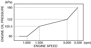
Engine oil pressure control circuit low oil pressure
|
• The engine oil pressure is the specification or less after the specified time has elapsed since the engine was started.
-
― Engine speed is 1,000 rpm or less: 80 kPa
― Engine speed is 1,000—1,500 rpm: 80—105.5 kPa (engine speed is proportional to specification of engine oil pressure)
― Engine speed is 1,500—3,000 rpm: 105.5—122 kPa (engine speed is proportional to specification of engine oil pressure)
― Engine speed is 3,000—3,500 rpm: 122—180 kPa (engine speed is proportional to specification of engine oil pressure)
― Engine speed is 3,500 rpm or more: 180 kPaCharacteristic graph (reference)
|
|
P057F:00
|
Power system: Battery deterioration
|
• The battery charge/discharge flow exceeds the specified value.
|
|
P058A:00
|
Current sensor: Function malfunction
|
• Error signal from the current sensor is received.
|
|
P0600:00
|
Serial communication link
|
• There is a communication error in the PCM.
|
|
P0601:00
|
PCM memory check sum error
|
• There is a malfunction in the PCM.
|
|
P0602:00
|
PCM programming error
|
• With the following conditions met, the vehicle recognition is not stored in the PCM for a continuous 1 s.
-
― Ignition is switched ON (engine off or on)
|
|
P0605:00
|
PCM memory check sum error
|
• Error in PCM internal memory is detected 2 times continuously.
|
|
P0606:00
|
PCM processor error
|
• The PCM internal main processor has a malfunction.
|
|
P0607:00
|
Control module performance problem
|
• The CPU which monitors the PCM internal main processor has a malfunction.
|
|
P060B:00
|
PCM internal malfunction
|
• There is a circuit malfunction in the PCM.
|
|
P0610:00
|
PCM vehicle configuration error
|
• With the following conditions met, the vehicle recognition is not correctly stored in the PCM for a continuous 1 s.
-
― Ignition is switched ON (engine off or on)
|
|
P0615:00
|
Starter relay circuit problem
|
• When the number of times the engine has been started has reached the warrantied performance frequency for the starter or starter relay.
|
|
P0628:00
|
Suction control valve circuit low input
|
• With the following conditions met, a condition has continued for 1 s in which the suction control valve control current is 1.0 A or less or the control voltage is more than the specified value.
-
― Battery voltage: 8—16 V
― 0.5 s have elapsed after ignition is switched ON (engine on)
― Suction control valve control duty value: 100%
― The following DTCs are not detected
-
• Suction control valve: P0629:00
|
|
P0629:00
|
Suction control valve circuit high input
|
• With the following conditions met, a condition has continued for 1 s in which the suction control valve control voltage is the specified value or less or the control current exceeds 1.0 A.
-
― Battery voltage: 8—16 V
― 0.5 s have elapsed after ignition is switched ON (engine on)
― Suction control valve control duty value: 0 %
― The following DTCs are not detected
-
• Suction control valve: P0628:00
|
|
P062B:00
|
PCM internal malfunction
|
• With the following conditions met, a malfunction with the processor in the PCM is detected.
-
― Battery positive voltage: 8.0 V or more
|
|
P0642:00
|
Constant voltage power supply circuit low input
|
• When the following condition is met, the output voltage of the constant voltage (5 V) power supply terminal is less than 2.36 V for a continuous 0.5 s.
-
― Battery positive voltage: 8—16 V
|
|
P0643:00
|
Constant voltage power supply circuit high input
|
• When the following condition is met, the output voltage of the constant voltage (5 V) power supply terminal exceeds 5.96 V for a continuous 0.5 s.
-
― Battery positive voltage: 8—16 V
|
|
P0646:00
|
A/C relay circuit low input
|
• When all of the following conditions are met, a condition whereby the A/C relay control circuit voltage is less than the specification continues for 5 s.
-
― Battery positive voltage: 8—16 V
― 0.5 s have elapsed after ignition is switched ON (engine off or on)
― During A/C relay off control
|
|
P0647:00
|
A/C relay circuit high input
|
• When all of the following conditions are met, a condition whereby the A/C relay control circuit current is the specification or more continues for 5 s.
-
― Battery positive voltage: 9—16 V
― 0.5 s have elapsed after ignition is switched ON (engine off or on)
― During A/C relay on control
|
|
P064D:00
|
A/F sensor control device in PCM: Run error
|
• There is a communication error in the PCM.
|
|
P0652:00
|
Constant voltage power supply circuit low input
|
• When the following condition is met, the output voltage of the 5 V power supply terminal is less than 2.36 V for a continuous 0.5 s.
-
― Battery positive voltage: 8—16 V
|
|
P0653:00
|
Constant voltage power supply circuit high input
|
• When the following condition is met, the output voltage of the 5 V power supply terminal exceeds 5.96 V for a continuous 0.5 s.
-
― Battery positive voltage: 8—16 V
|
|
P0668:00
|
PCM internal temperature sensor circuit low input
|
• With the following conditions met, the BARO pressure sensor (PCM integrated) output value is 0.10 V or lessfor a continuous 5 s.
-
― Battery voltage: 8—16 V
― 0.5 s have elapsed after ignition is switched ON (engine on)
|
|
P0669:00
|
PCM internal temperature sensor circuit high input
|
• PCM temperature is abnormally high when the following conditions are met:
-
― Battery voltage: 8—16 V
― 0.5 s have elapsed after ignition is switched ON (engine on)
|
|
P0670:00
|
Glow control module control circuit problem
|
• When the following conditions are met, a condition continues for 5 s in which the power supply voltage of the glow control module is less than 5.8 V or exceeds 16.5 V, or there is an internal circuit malfunction, or the temperature of the internal circuit exceeds the specification.
-
― During glow control
― Glow plug circuit voltage: 3—11.3 V
|
|
P0671:00
|
Glow plug No.1 control circuit problem
|
• When the following conditions are met, a condition continues for 5 s in which the current at the glow plug No.1 circuit is less than 2.88 A during glow control at 75 % or more of battery voltage, or glow control exceeding 65 A at less than 75 % of battery voltage.
-
― During glow control
― Glow plug No.1 circuit voltage: 3—11.3 V
|
|
P0672:00
|
Glow plug No.2 control circuit problem
|
• When the following conditions are met, a condition continues for 5 s in which the current at the glow plug No.2 circuit is less than 2.88 A during glow control at 75 % or more of battery voltage, or glow control exceeding 65 A at less than 75 % of battery voltage.
-
― During glow control
― Glow plug No.2 circuit voltage: 3—11.3 V
|
|
P0673:00
|
Glow plug No.3 control circuit problem
|
• When the following conditions are met, a condition continues for 5 s in which the current at the glow plug No.3 circuit is less than 2.88 A during glow control at 75 % or more of battery voltage, or glow control exceeding 65 A at less than 75 % of battery voltage.
-
― During glow control
― Glow plug No.3 circuit voltage: 3—11.3 V
|
|
P0674:00
|
Glow plug No.4 control circuit problem
|
• When the following conditions are met, a condition continues for 5 s in which the current at the glow plug No.4 circuit is less than 2.88 A during glow control at 75 % or more of battery voltage, or glow control exceeding 65 A at less than 75 % of battery voltage.
-
― During glow control
― Glow plug No.4 circuit voltage: 3—11.3 V
|
|
P06B8:00
|
Internal control module non-volatile RAM error
|
• There is a malfunction in the PCM.
|
|
P06DB:00
|
Engine oil solenoid valve circuit low input
|
• The engine oil solenoid valve control voltage is less than the specified value for a continuous 5 s when the following conditions are met:
-
― Battery positive voltage: 8—16 V
― 0.5 s have elapsed after ignition is switched ON (engine off or on)
|
|
P06DC:00
|
Engine oil solenoid valve control circuit high input
|
• The engine oil solenoid valve control voltage exceeds the specified value for a continuous 5 s when the following conditions are met:
-
― Battery positive voltage: 8.0—16 V
― 0.5 s have elapsed after ignition is switched ON (engine off or on)
|
|
P06DD:00
|
Engine oil pressure switch control circuit high input
|
• With the following conditions met, the engine oil pressure exceeds 230 kPa for a continuous 5 s.
-
― Engine oil temperature sensor: Normal
― Engine oil pressure sensor: Normal
― During low hydraulic pressure control (during engine oil solenoid valve operation)
― Engine oil temperature is 20 °C or more
― Engine speed is specification or more:
-
• 7,50 rpm or more when engine oil temperature is 20 °C (when cold)
• 2,000 rpm or more when engine oil temperature is 90 °C (when hot)
• 4,000 rpm or more when engine oil temperature is 140 °C or more (when extremely hot)
|
|
P06DE:00
|
Engine oil pressure switch control circuit low input
|
• With the following conditions met, the engine oil pressure is 230 kPa or less for a continuous 5 s.
-
― Engine oil temperature sensor: Normal
― Engine oil pressure sensor: Normal
― During high hydraulic pressure control (during engine oil solenoid valve operation)
― Engine oil temperature is 20 °C or more
― Engine speed is specification or more:
-
• 7,50 rpm or more when engine oil temperature is 20 °C (when cold)
• 2,000 rpm or more when engine oil temperature is 90 °C (when hot)
• 4,000 rpm or more when engine oil temperature is 140 °C or more (when extremely hot)
|
|
P0703:00
|
Brake switch input circuit problem
|
• Decelerate the vehicle at a rate exceeding 2.35 km/h per second from a vehicle speed condition of 30 km/h or more, and stop the vehicle. The brake switch signal does not change even if this operation is repeated 8 times.
-
― The following DTCs are not detected
-
• Vehicle speed signal: P0500:00
|
|
P0A0F:00
|
Engine failed to restart
|
• When any of the following conditions is met:
-
― When the engine should restart after it is stopped by the i-stop control, it does not start even though it is cranked for 3 s or more.
― Engine does not crank when the engine is stopped and started by the i-stop control.
|
|
P0A8D:00
|
Power supply system circuit low input
|
• The battery positive voltage, the voltage for the PCM control, or the voltage for the DC-DC converter control is low when the engine is started.
|
|
P0A8F:00
|
Power system: Low input
|
• When any of the following conditions is met:
-
― Battery voltage is 11 V or less when ignition is switched OFF after leaving vehicle for 30 days or more.
― Battery voltage is 11 V or less with ignition switched OFF for a continuous 5 days.
|
|
P1041:00
|
Cylinder No.1: Function malfunction
|
• With all of the following conditions met, the PCM determines that the control signal received from fuel injector No.1 is not operating normally 255 times consecutively.
-
― Battery voltage: 10.5―18.0 V
― diesel particulate filter regeneration control is not performed
― ECT sensor No.1: 5 °C or more
― Actual fuel temperature: 5 °C or more
― Actual fuel pressure: 35—217 MPa
― The following DTCs are not detected
-
• Fuel pressure sensor: P10C1:00, P10C2:00, P10C3:00, P10C7:00, P10C8:00, P10C9:00, P10CD:00
• Fuel temperature sensor: P10D1:00, P10D3:00, P10D5:00
• Fuel injector: P0201:00, P2146:00, P2147:00, P2148:00, P1379:00, P2696:00, P268C:0, P268E:00
• LIN communication system: U1201:00, U1202:00, U1203:00, U1204:00
• ECT sensor: P0118:00, P0117:00
• Malfunction in PCM: P062B:00
|
|
P1042:00
|
Cylinder No.2: Function malfunction
|
• With all of the following conditions met, the PCM determines that the control signal received from fuel injector No.2 is not operating normally 255 times consecutively.
-
― Battery positive voltage: 10.5—18.0 V
― diesel particulate filter regeneration control is not performed
― ECT sensor No.1: 5 °C or more
― Actual fuel temperature: 5 °C or more
― Actual fuel pressure: 35—217 MPa
― The following DTCs are not detected
-
• Fuel pressure sensor: P10C1:00, P10C2:00, P10C3:00, P10C4:00, P10C5:00, P10C6:00, P10CD:00
• Fuel temperature sensor: P10D1:00, P10D2:00, P10D5:00
• Fuel injector: P0202:00, P2149:00, P2150:00, P2151:00, P1379:00, P2696:00, P268C:0, P268D:00
• LIN communication system: U1201:00, U1202:00, U1203:00, U1204:00
• ECT sensor: P0118:00, P0117:00
• Malfunction in PCM: P0606:00, P062B:00
|
|
P1043:00
|
Cylinder No.3: Function malfunction
|
• With all of the following conditions met, the PCM determines that the control signal received from fuel injector No.3 is not operating normally 255 times consecutively.
-
― Battery positive voltage: 10.5—18.0 V
― diesel particulate filter regeneration control is not performed
― ECT sensor No.1: 5 °C or more
― Actual fuel temperature: 5 °C or more
― Actual fuel pressure: 35—217 MPa
― The following DTCs are not detected
-
• Fuel pressure sensor: P10C7:00, P10C8:00, P10C9:00, P10CA:00, P10CB:00, P10CC:00, P10CD:00
• Fuel temperature sensor: P10D3:00, P10D4:00, P10D5:00
• Fuel injector: P0203:00, P2149:00, P2150:00, P2151:00, P1379:00, P2696:00, P268E:00, P268F:00
• LIN communication system: U1201:00, U1202:00, U1203:00, U1204:00
• ECT sensor: P0118:00, P0117:00
• Malfunction in PCM: P0606:00, P062B:00
|
|
P1044:00
|
Cylinder No.4: Function malfunction
|
• With all of the following conditions met, the PCM determines that the control signal received from fuel injector No.4 is not operating normally 255 times consecutively.
-
― Battery positive voltage: 10.5—18.0 V
― diesel particulate filter regeneration control is not performed
― ECT sensor No.1: 5 °C or more
― Actual fuel temperature: 5 °C or more
― Actual fuel pressure: 35—217 MPa
― The following DTCs are not detected
-
• Fuel pressure sensor: P10C4:00, P10C5:00, P10C6:00, P10CA:00, P10CB:00, P10CC:00, P10CD:00
• Fuel temperature sensor: P10D2:00, P10D4:00, P10D5:00
• Fuel injector: P0204:00, P2146:00, P2147:00, P2148:00, P1379:00, P2696:00, P268D:00, P268F:00
• LIN communication system: U1201:00, U1202:00, U1203:00, U1204:00
• ECT sensor: P0118:00, P0117:00
• Malfunction in PCM: P0606:00, P062B:00
|
|
P10C1:00
|
Fuel pressure sensor(integrated with fuel injector No.1) circuit range/performance problem
|
• With all of the following conditions met, the PCM detects that the difference between the value of the fuel pressure sensor (integrated with fuel injector No.1) and the value of the fuel pressure sensor for each cylinder is 33 MPa or more 6 times consecutively.
-
― Battery positive voltage: 8.0 V or more
― diesel particulate filter regeneration control is not performed
― 0.5 s have elapsed after ignition is switched ON (engine off or on)
― The following DTCs are not detected
-
• Fuel pressure sensor: P10C2:00, P10C3:00, P10C5:00, P10C6:00, P10C8:00, P10C9:00, P10CB:00, P10CC:00
• Fuel injector: P2696:00, P268C:00, P268D:00, P268E:00, P268F:00
• LIN communication system: U1201:00, U1202:00, U1203:00, U1204:00
|
|
P10C2:00
|
Fuel pressure sensor(integrated with fuel injector No.1) circuit low input
|
• With the following conditions met, the fuel pressure sensor output voltage is 0.37 V or less for a continuous 0.7 s.
-
― Battery positive voltage: 8.0 V or more
― Specified time has elapsed after ignition is switched ON (engine off or on)
|
|
P10C3:00
|
Fuel pressure sensor(integrated with fuel injector No.1) circuit high input
|
• With the following conditions met, the fuel pressure sensor output voltage is 4.15 V or more for a continuous 0.7 s.
-
― Battery positive voltage: 8.0 V or more
― Specified time has elapsed after ignition is switched ON (engine off or on)
|
|
P10C4:00
|
Fuel pressure sensor(integrated with fuel injector No.2) circuit range/performance problem
|
• With all of the following conditions met, the PCM detects that the difference between the value of the fuel pressure sensor (integrated with fuel injector No.2) and the value of the fuel pressure sensor for each cylinder is 33 MPa or more6 times consecutively.
-
― Battery positive voltage: 8.0 V or more
― diesel particulate filter regeneration control is not performed
― Specified time has elapsed after ignition is switched ON (engine off or on)
― The following DTCs are not detected
-
• Fuel pressure sensor: P10C2:00, P10C3:00, P10C5:00, P10C6:00, P10C7:00, P10C8:00, P10C9:00, P10CA:00, P10CB:00, P10CC:00
• Fuel injector: P2696:00, P268C:00, P268D:00, P268E:00, P268F:00
• LIN communication system: U1201:00, U1202:00, U1203:00, U1204:00
|
|
P10C5:00
|
Fuel pressure sensor(integrated with fuel injector No.2) circuit low input
|
• With the following conditions met, the fuel pressure sensor output voltage is 0.37 V or less for a continuous 0.7 s.
-
― Battery positive voltage: 8.0 V or more
― Specified time has elapsed after ignition is switched ON (engine off or on)
|
|
P10C6:00
|
Fuel pressure sensor(integrated with fuel injector No.2) circuit high input
|
• With the following conditions met, the fuel pressure sensor output voltage is 4.15 V or more for a continuous 0.7 s.
-
― Battery positive voltage: 8.0 V or more
― Specified time has elapsed after ignition is switched ON (engine off or on)
|
|
P10C7:00
|
Fuel pressure sensor(integrated with fuel injector No.3) circuit range/performance problem
|
• With all of the following conditions met, the PCM detects that the difference between the value of the fuel pressure sensor (integrated with fuel injector No.3) and the value of the fuel pressure sensor for each cylinder is 33 MPa or more 6 times consecutively.
-
― Battery positive voltage: 8.0 V or more
― diesel particulate filter regeneration control is not performed
― Specified time has elapsed after ignition is switched ON (engine off or on)
― The following DTCs are not detected
-
• Fuel pressure sensor: P10C2:00, P10C3:00, P10C5:00, P10C6:00, P10C8:00, P10C9:00, P10CB:00, P10CC:00
• Fuel injector: P2696:00, P268C:00, P268D:00, P268E:00, P268F:00
• LIN communication system: U1201:00, U1202:00, U1203:00, U1204:00
|
|
P10C8:00
|
Fuel pressure sensor(integrated with fuel injector No.3) circuit low input
|
• With the following conditions met, the fuel pressure sensor output voltage is 0.37 V or less for a continuous 0.7 s.
-
― Battery positive voltage: 8.0 V or more
― Specified time has elapsed after ignition is switched ON (engine off or on)
|
|
P10C9:00
|
Fuel pressure sensor(integrated with fuel injector No.3) circuit high input
|
• With the following conditions met, the fuel pressure sensor output voltage is 4.15 V or more for a continuous 0.7 s.
-
― Battery positive voltage: 8.0 V or more
― Specified time has elapsed after ignition is switched ON (engine off or on)
|
|
P10CA:00
|
Fuel pressure sensor(integrated with fuel injector No.4) circuit range/performance problem
|
• With all of the following conditions met, the PCM detects that the difference between the value of the fuel pressure sensor (integrated with fuel injector No.4) and the value of the fuel pressure sensor for each cylinder is 33 MPa or more 6 times consecutively.
-
― Battery positive voltage: 8.0 V or more
― diesel particulate filter regeneration control is not performed
― Specified time has elapsed after ignition is switched ON (engine off or on)
― The following DTCs are not detected
-
• Fuel pressure sensor: P10C2:00, P10C3:00, P10C4:00, P10C5:00, P10C6:00, P10C8:00, P10C9:00, P10CB:00, P10CC:00
• Fuel injector: P2696:00, P268C:00, P268D:00, P268E:00, P268F:00
• LIN communication system: U1201:00, U1202:00, U1203:00, U1204:00
|
|
P10CB:00
|
Fuel pressure sensor(integrated with fuel injector No.4) circuit low input
|
• With the following conditions met, the fuel pressure sensor output voltage is 0.37 V or less for a continuous 0.7 s.
-
― Battery positive voltage: 8.0 V or more
― Specified time has elapsed after ignition is switched ON (engine off or on)
|
|
P10CC:00
|
Fuel pressure sensor(integrated with fuel injector No.4) circuit high input
|
• With the following conditions met, the fuel pressure sensor output voltage is 4.15 V or more for a continuous 0.7 s.
-
― Battery positive voltage: 8.0 V or more
― Specified time has elapsed after ignition is switched ON (engine off or on)
|
|
P10CD:00
|
Fuel pressure sensor circuit range/performance problem
|
• With all of the following conditions met, the output values of the fuel pressure sensor for each cylinder are compared, and the PCM detects that the difference is 25 MPa or more6 times consecutively.
-
― Battery positive voltage: 8.0 V or more
― diesel particulate filter regeneration control is not performed
― Specified time has elapsed after ignition is switched ON (engine off or on)
― The following DTCs are not detected
-
• Fuel pressure sensor: P10C2:00, P10C3:00, P10C5:00, P10C6:00, P10C8:00, P10C9:00, P10CB:00, P10CC:00
• Fuel injector: P2696:00, P268C:00, P268D:00, P268E:00, P268F:00
• LIN communication system: U1201:00, U1202:00, U1203:00, U1204:00
|
|
P10D1:00
|
Fuel temperature sensor(integrated with fuel injector No.1) circuit range/performance problem
|
• With all of the following conditions met, the PCM detects that the difference between the value of the fuel temperature sensor (integrated with fuel injector No.1) and the value of the fuel temperature sensor for each cylinder is 23.6 °C or more for 6 s.
-
― Battery positive voltage: 10.5—18.0 V
― The following DTCs are not detected
-
• Fuel pressure sensor: P10C2:00, P10C3:00, P10C5:00, P10C6:00, P10C8:00, P10C9:00, P10CB:00, P10CC:00
• Fuel injector: P2696:00, P268C:00, P268D:00, P268E:00, P268F:00
• LIN communication system: U1201:00, U1202:00, U1203:00, U1204:00
|
|
P10D2:00
|
Fuel temperature sensor(integrated with fuel injector No.2) circuit range/performance problem
|
• With all of the following conditions met, the PCM detects that the difference between the value of the fuel temperature sensor (integrated with fuel injector No.2) and the value of the fuel temperature sensor for each cylinder is 23.6 °C or more for 6 s.
-
― Battery positive voltage: 10.5—18.0 V
― The following DTCs are not detected
-
• Fuel pressure sensor: P10C2:00, P10C3:00, P10C5:00, P10C6:00, P10C8:00, P10C9:00, P10CB:00, P10CC:00
• Fuel injector: P2696:00, P268C:00, P268D:00, P268E:00, P268F:00
• LIN communication system: U1201:00, U1202:00, U1203:00, U1204:00
|
|
P10D3:00
|
Fuel temperature sensor(integrated with fuel injector No.3) circuit range/performance problem
|
• With all of the following conditions met, the PCM detects that the difference between the value of the fuel temperature sensor (integrated with fuel injector No.3) and the value of the fuel temperature sensor for each cylinder is 23.6 °C or more for 6 s.
-
― Battery positive voltage: 10.5—18.0 V
― The following DTCs are not detected
-
• Fuel pressure sensor: P10C2:00, P10C3:00, P10C5:00, P10C6:00, P10C8:00, P10C9:00, P10CB:00, P10CC:00
• Fuel injector: P2696:00, P268C:00, P268D:00, P268E:00, P268F:00
• LIN communication system: U1201:00, U1202:00, U1203:00, U1204:00
|
|
P10D4:00
|
Fuel temperature sensor(integrated with fuel injector No.4) circuit range/performance problem
|
• With all of the following conditions met, the PCM detects that the difference between the value of the fuel temperature sensor (integrated with fuel injector No.4) and the value of the fuel temperature sensor for each cylinder is 23.6 °C or more for 6 s.
-
― Battery positive voltage: 10.5—18.0 V
― The following DTCs are not detected
-
• Fuel pressure sensor: P10C2:00, P10C3:00, P10C5:00, P10C6:00, P10C8:00, P10C9:00, P10CB:00, P10CC:00
• Fuel injector: P2696:00, P268C:00, P268D:00, P268E:00, P268F:00
• LIN communication system: U1201:00, U1202:00, U1203:00, U1204:00
|
|
P10D5:00
|
Fuel temperature sensor circuit range/performance problem
|
• With all of the following conditions met, the value of the fuel temperature sensor for each cylinder and the value of the fuel temperature sensor are compared, and the PCM detects that the difference is 23.6 °C or more for 2 cylinders or more for 6 s.
-
― Battery positive voltage: 10.5—18.0 V
― The following DTCs are not detected
-
• Fuel pressure sensor: P10C2:00, P10C3:00, P10C5:00, P10C6:00, P10C8:00, P10C9:00, P10CB:00, P10CC:00
• Fuel injector: P2696:00, P268C:00, P268D:00, P268E:00, P268F:00
• LIN communication system: U1201:00, U1202:00, U1203:00, U1204:00
|
|
P1118:00
|
IAT sensor No.2 circuit low input
|
• With the following conditions met, the intake air temperature sensor No.2 output voltage is less than 0.29 V for a continuous 0.6 s.
-
― Battery voltage: 8—16 V
― 0.5 s have elapsed after ignition is switched ON (engine off or on)
|
|
P1119:00
|
IAT sensor No.2 circuit high input
|
• With the following conditions met, the IAT sensor No.2 output voltage exceeds 4.94 V for a continuous 0.6 s.
-
― Battery voltage: 8—16 V
― 0.5 s have elapsed after ignition is switched ON (engine off or on)
|
|
P111A:00
|
Engine coolant temperature is high
|
• Engine coolant temperature of 110 °C or more continues for 2.5 s or more.
|
|
P1140:00
|
Sedimentor switch control circuit range/performance problem
|
• Water accumulated in the fuel filter is the specified amount or more. (In this case, sedimentor switch is on)
|
|
P1142:00
|
Fuel injection amount system: Output restriction
|
• When any of the following conditions is met:
-
― Output value of exhaust gas pressure sensor No.1 is specified value or more
― Turbocharger control system: Overboost
|
|
P1147:00
|
IAT sensor No.2 correlation problem
|
• With the following conditions met, the difference between the IAT sensor No.2 output value and the boost air temperature sensor output value is 150 °C or more, or the difference between the IAT sensor No.1 output value and the IAT sensor No.2 output value is 150 °C or more for a continuous 0.128 s.
-
― Before starting the engine, leave the vehicle with the engine turned off for 6 h or more.
― Battery positive voltage: 10 V or more
― Ignition is switched ON (engine off or on)
― The following DTCs are not detected
-
• Boost air temperature sensor: P007C:00, P007D:00
• IAT sensor No.1: P0112:00, P0113:00
• IAT sensor No.2: P1118:00, P1119:00
• Malfunction in instrument cluster: P2610:00
• ECT sensor: P0118:00, P0117:00
|
|
P115A:00
|
Lack of remaining fuel (output restriction)
|
• “Injection amount cumulative value after lowering point E“, which is calculated by the PCM, exceeds the threshold value.
|
|
P115B:00
|
Lack of remaining fuel (fuel injection pause)
|
• “Injection amount cumulative value after lowering point E”, which is calculated by the PCM, exceeds the threshold value (larger than P0313:00).
|
|
P117A:00
|
Record of torque restriction for piston protection
|
• The engine oil pressure is the specification or less for a continuous 8 s or more.
|
|
P1200:00
|
Fuel injection amount learning not completed
|
• Fuel injection amount learning is not completed normally.
|
|
P1260:00
|
Immobilizer system problem
|
• If the stop start unit detects a malfunction in the immobilizer system.
|
|
P1282:00
|
Common rail control system problem
|
• With the following conditions met, the fuel pressure value in the common rail exceeds 250 MPa or exceeds the fuel pressure value calculated by the PCM based on the engine speed for a continuous 1 s.
-
― Battery voltage: 8—16 V
― 0.5 s have elapsed after ignition is switched ON (engine on)
― Engine speed: 500 rpm or more
― The following DTCs are not detected
-
• Fuel pressure sensor: P01C6:00, P01C5:00, P018D:00, P018C:00, P10CD:00
|
|
P1329:00
|
Common rail pressure higher than desired (engine running)
|
• With the following conditions met, the fuel pressure value in the common rail exceeds 250 MPa or exceeds the fuel pressure value calculated by the PCM based on the engine speed for a continuous 1 s.
-
― Battery voltage: 8—16 V
― 0.5 s have elapsed after ignition is switched ON (engine on)
• With the following conditions met, the fuel pressure value in the common rail exceeds 217 MPa or exceeds the fuel pressure value calculated by the PCM based on the engine speed for a continuous 60 s.
-
― Battery voltage: 8—16 V
― 0.5 s have elapsed after ignition is switched ON (engine on)
― The following DTCs are not detected
-
• Fuel pressure sensor: P01C6:00, P01C5:00, P018D:00, P018C:00, P10CD:00
|
|
P1336:00
|
CKP sensor/CMP sensor malfunction
|
• The phase difference between the CKP sensor and the CMP sensor exceeds the specification. (Determines stretched timing chain)
|
|
P1378:00
|
Fuel injector circuit low input
|
• The PCM detected that the voltage output from the boost circuit for the fuel injector control built into the PCM is less than 120 V when all of the following conditions are met.
-
― Battery positive voltage: 8.0 V or more
|
|
P1379:00
|
Fuel injector circuit high input
|
• The PCM detected that the voltage output from the boost circuit for the fuel injector control built into the PCM exceeds 250 V when all of the following conditions are met.
-
― Battery positive voltage: 8.0 V or more
|
|
P1589:00
|
Intake shutter valve circuit range/performance problem
|
• With the following conditions met, the difference between the target intake shutter valve opening angle and the actual value exceeds 4.2° for a continuous 2 s.
-
― Battery voltage: 8—16 V
― 0.5 s have elapsed after ignition is switched ON (engine off or on)
― The following DTCs are not detected
-
• Constant voltage power supply control system: P0653:00, P0652:00
• Intake shutter valve position sensor: P0122:00, P0123:00
• Intake shutter valve control system: P2101:00
|
|
P161E:00
|
Exhaust gas temperature sensor No.2: Transistor in PCM stuck on malfunction
|
• With the following conditions met, the exhaust gas temperature sensor No.2 output voltage is 4.85 V or more for a continuous 6 s.
-
― Battery voltage: 8.0―16 V
― Transistor command value: OFF
|
|
P161F:00
|
Exhaust gas temperature sensor No.3: Transistor in PCM stuck on malfunction
|
• With the following conditions met, the exhaust gas temperature sensor No.3 output voltage is 4.85 V or more for a continuous 6 s.
-
― Battery voltage: 8.0—16 V
― Transistor command value: OFF
|
|
P167B:00
|
Fuel injection amount learning not completed in fuel injection system
|
• Fuel injection amount learning is not completed
|
|
P16A0:00
|
Intake shutter valve control device in PCM: Run error
|
• Malfunction occurred in the signal circuit of the intake shutter valve in the PCM.
|
|
P16A1:00
|
EGR valve control device in PCM: Run error
|
• Malfunction occurred in signal circuit of EGR valve control device in PCM.
|
|
P16A2:00
|
EGR cooler bypass valve control device in PCM: Run error
|
• Malfunction occurred in the signal circuit of the EGR cooler bypass valve control device in the PCM.
|
|
P16A5:00
|
Regulating valve control device in PCM: Run error
|
• Malfunction occurred in the signal circuit of the regulating valve in the PCM.
|
|
P16A6:00
|
Variable turbine geometry turbocharger actuator control system in PCM: Run error
|
• Malfunction occurred in signal circuit of the variable turbine geometry turbocharger actuator in the PCM.
|
|
P16A7:00
|
Coolant control valve control device in PCM: Run error
|
• Malfunction in coolant control valve signal circuit in PCM occurs.
|
|
P16AB:00
|
PCM internal malfunction
|
• Sub-processor in PCM has a malfunction.
|
|
P16B2:00
|
Exhaust gas temperature sensor No.2: Transistor in PCM stuck off malfunction
|
• With the following conditions met, the exhaust gas temperature sensor No.2 output voltage is 2.1 V or less for a continuous 6 s.
-
― Battery voltage: 8.0―16 V
― Transistor command value: ON
|
|
P16B3:00
|
Exhaust gas temperature sensor No.3: Transistor in PCM stuck off malfunction
|
• With the following conditions met, the exhaust gas temperature sensor No.3 output voltage is 2.1 V or less for a continuous 6 s.
-
― Battery voltage: 8.0―16 V
― Transistor command value: ON
|
|
P1905:00
|
Check connector circuit low input
|
• A check connector voltage approx. 0 V condition continues for 16 msec.
|
|
P2002:00
|
Diesel particulate filter function decreased
|
• The difference in the pressure before and after passing the diesel particulate filter of less than the specified value is detected for 2s.
|
|
P2031:00
|
Exhaust gas temperature sensor No.2 correlation problem
|
• With the following conditions met, the difference between the exhaust gas temperature sensor No.1 output value and the exhaust gas temperature sensor No.2 output value is 150 °C or more, or the difference between the exhaust gas temperature sensor No.2 output value and the exhaust gas temperature sensor No.3 output value is 150 °C or more for a continuous 0.128 s.
-
― Before starting the engine, leave the vehicle with the engine turned off for 6 h or more.
― Battery positive voltage: 10 V or more
― Ignition is switched ON (engine off or on)
― The following DTCs are not detected
-
• ECT sensor: P0118:00, P0117:00
• Exhaust gas temperature sensor No.2: P2032:00, P2033:00
• Exhaust gas temperature sensor No.1: P0545:00, P0546:00
• Malfunction in instrument cluster: P2610:00
• Exhaust gas temperature sensor No.3: P242C:00, P242D:00
• Exhaust gas temperature sensor No.2 transistor: P161E:00, P16B2:00
• Exhaust gas temperature sensor No.3 transistor: P161F:00, P16B3:00
|
|
P2032:00
|
Exhaust gas temperature sensor No.2 circuit low input
|
• With the following conditions met, the exhaust gas temperature sensor No.2 output voltage is less than 0.08 V for a continuous 5 s.
-
― Battery positive voltage: 8—16 V
― 0.5 s have elapsed after ignition is switched ON (engine off or on)
|
|
P2033:00
|
Exhaust gas temperature sensor No.2 circuit high input
|
• With the following conditions met, the exhaust gas temperature sensor No.2 output voltage exceeds 4.65 V for a continuous 5 s.
-
― Battery voltage: 8—16 V
|
|
P2080:00
|
Exhaust gas temperature sensor No.1 circuit range/performance problem
|
• With the following conditions met, the difference between the exhaust gas temperature sensor No.1 output value and the exhaust gas temperature sensor No.2 output value is 150 °C or more, or the difference between the exhaust gas temperature sensor No.1 output value and the exhaust gas temperature sensor No.3 output value is 150 °C or more for a continuous 0.128 s.
-
― Before starting the engine, leave the vehicle with the engine turned off for 6 h or more.
― Battery positive voltage: 10 V or more
― Ignition is switched ON (engine off or on)
― The following DTCs are not detected
-
• ECT sensor: P0118:00, P0117:00
• Exhaust gas temperature sensor No.2: P2032:00, P2033:00
• Exhaust gas temperature sensor No.1: P0545:00, P0546:00
• Malfunction in instrument cluster: P2610:00
• Exhaust gas temperature sensor No.3: P242C:00, P242D:00
• Exhaust gas temperature sensor No.2 transistor: P161E:00, P16B2:00
• Exhaust gas temperature sensor No.3 transistor: P161F:00, P16B3:00
|
|
P2101:00
|
Intake shutter valve control circuit overcurrent
|
• With the following conditions met, a condition has continued for 2 s in which the drive current of the intake shutter valve exceeds the specification or the temperature of the DC motor drive circuit is 170 °C or more.
-
― Battery positive voltage: 8—16 V
― 0.5 s elapses after engine is started
|
|
P2104:00
|
Intake shutter valve control system: Idle restriction
|
• When the following conditions are met, the PCM determines that the exhaust gas pressure or boost pressure is the estimated value or more.
-
― Ignition is switched ON (engine running)
― Selector lever position: P or N position
|
|
P2105:00
|
Intake air shutter valve actuator control system malfunction (forced engine shutdown)
|
• After switching the ignition off, the PCM detects that the engine speed has not decreased for a specified time.
|
|
P2106:00
|
Intake shutter valve control system: Output restriction
|
• Exhaust gas pressure or boost pressure of estimated value or more is detected
|
|
P2118:00
|
Intake shutter valve control duty signal error
|
• The intake air shutter valve actuator control duty value is 90 % or more for a continuous 2 s.
-
― The following DTCs are not detected
-
• Intake shutter valve position sensor: P0122:00, P0123:00
• Intake shutter valve control system: P1589:00, P2101:00
• Intake shutter valve control device in PCM: P16A0:00
|
|
P2122:00
|
APP sensor No.1 circuit low input
|
• With the following conditions met, the output voltage of APP sensor No.1 is less than 0.25 V for a continuous 0.5 s.
-
― Battery positive voltage: 8—16 V
― 0.5 s have elapsed after ignition is switched ON (engine off or on)
― The following DTCs are not detected
-
• Constant voltage power supply control system: P0642:00, P0643:00
|
|
P2123:00
|
APP sensor No.1 circuit high input
|
• With the following conditions met, the output voltage of APP sensor No.1 exceeds 4.77 V for a continuous 0.5 s.
-
― Battery positive voltage: 8—16 V
― Ignition is switched ON (engine off or on)
― The following DTCs are not detected
-
• Constant voltage power supply control system: P0642:00, P0643:00
|
|
P2127:00
|
APP sensor No.2 circuit low input
|
• With the following conditions met, the output voltage of APP sensor No.2 is less than 0.13 V for a continuous 0.5 s.
-
― Battery positive voltage: 8—16 V
― 0.5 s have elapsed after ignition is switched ON (engine off or on)
― The following DTCs are not detected
-
• Constant voltage power supply control system: P0652:00, P0653:00
|
|
P2128:00
|
APP sensor No.2 circuit high input
|
• With the following conditions met, the output voltage of APP sensor No.2 exceeds 4.13 V for a continuous 0.5 s.
-
― Battery positive voltage: 8—16 V
― Ignition is switched ON (engine off or on)
― The following DTCs are not detected
-
• Constant voltage power supply control system: P0652:00, P0653:00
|
|
P2138:00
|
APP sensor No.1/No.2 correlation problem
|
• With the following conditions met, the output voltages of APP sensors No.1 and No.2 are compared, and the difference in the voltages is 0.7 V or more for a continuous 1 s.
-
― Battery positive voltage: 8—16 V
― Ignition is switched ON (engine off or on)
― The following DTCs are not detected
-
• APP sensor No.1: P2122:00, P2123:00
• APP sensor No.2: P2127:00, P2128:00
• Constant voltage power supply control system: P0642:00, P0643:00, P0652:00, P0653:00
|
|
P2146:00
|
Fuel injector No.1 and No.4 circuit abnormal operation
|
• When the following condition is met, the PCM detects that the control current at fuel injectors No.1 and No.4 is less than the specification 6 times.
-
― Battery positive voltage: 8 V or more
|
|
P2147:00
|
Fuel injector No.1 and No.4 circuit low input
|
• When the following condition is met, the PCM detects that the control current at fuel injectors No.1 and No.4 is 35 A or more or the control voltage is less than 40 V12 times.
-
― Battery positive voltage: 8 V or more
|
|
P2148:00
|
Fuel injector No.1 and No.4 circuit high input
|
• When the following condition is met, the PCM detects that the control current at fuel injectors No.1 and No.4 exceeds 10 A4 times.
-
― Battery positive voltage: 8 V or more
|
|
P2149:00
|
Fuel injector No.2 and No.3 circuit abnormal operation
|
• When the following condition is met, the PCM detects that the control current at fuel injectors No.2 and No.3 is less than the specification 6 times.
-
― Battery positive voltage: 8 V or more
|
|
P2150:00
|
Fuel injector No.2 and No.3 circuit low input
|
• When the following condition is met, the PCM detects that the control current at fuel injectors No.2 and No.3 is 35 A or more or the control voltage is less than 40 V12 times.
-
― Battery positive voltage: 8 V or more
|
|
P2151:00
|
Fuel injector No.2 and No.3 circuit high input
|
• When the following condition is met, the PCM detects that the control current at fuel injectors No.2 and No.3 exceeds 10 A4 times.
-
― Battery positive voltage: 8 V or more
|
|
P2226:00
|
BARO sensor circuit problem
|
• Malfunction in BARO sensor signal circuit in PCM occurs.
|
|
P2227:00
|
BARO sensor circuit range/performance problem
|
• With the following conditions met, the difference between the value detected by MAP sensor No.1 and the barometric pressure is 11.5 kPa or more, or the difference between the value detected by the BARO sensor and exhaust gas pressure sensor No.1 exceeds 55.8 kPa.
-
― Battery positive voltage: 10 V or more
― 7 to 9 s have elapsed after ignition is switched off
― The following DTCs are not detected
-
• MAP sensor No.2: P0107:00, P0108:00
-
• MAP sensor No.1: P0237:00, P0238:00
-
• Exhaust gas pressure sensor P0472:00, P0473:00
-
• BARO sensor: P2226:00, P2228:00, P2229:00
|
|
P2228:00
|
BARO sensor circuit low input
|
• With the following conditions met, the BARO pressure sensor output voltage is less than 40 kPafor a continuous 5 s.
-
― Battery voltage: 8—16 V
― 0.5 s have elapsed after ignition is switched ON (engine off or on)
|
|
P2229:00
|
BARO sensor circuit high input
|
• With the following conditions met, the BARO sensor voltage exceeds 114.9 kPa for a continuous 5 s.
-
― Battery positive voltage: 8—16 V
― 0.5 s have elapsed after ignition is switched ON (engine off or on)
|
|
P2238:00
|
A/F sensor plus current circuit: Low input
|
• With the following conditions met, the A/F sensor terminal B voltage is less than 0.584 V for a continuous 5 s.
-
― Battery positive voltage: 11—16 V
― 0.5 s have elapsed after ignition is switched ON (engine on)
|
|
P2239:00
|
A/F sensor plus current circuit: High input
|
• With the following conditions met, the A/F sensor terminal B voltage exceeds 4.74 V for a continuous 5 s.
-
― Battery positive voltage: 11—16 V
― 0.5 s have elapsed after ignition is switched ON (engine on)
|
|
P2252:00
|
A/F sensor minus current circuit: Low input
|
• With the following conditions met, any of the A/F sensor terminal D voltages is less than 0.479 V for a continuous 5 s.
-
― Battery positive voltage: 11—16 V
― 0.5 s have elapsed after ignition is switched ON (engine on)
|
|
P2253:00
|
A/F sensor minus current circuit: High input
|
• With the following conditions met, the A/F sensor terminal D voltage exceeds 4.57 V for a continuous 5 s.
-
― Battery positive voltage: 11—16 V
― 0.5 s have elapsed after ignition is switched ON (engine on)
|
|
P2299:00
|
Accelerator pedal: spring back malfunction
|
• A condition is detected in which the brake pedal is depressed * while the vehicle is driven under the following conditions.
Vehicle is being driven
-
― Other than idling
― Engine speed: 875 rpm or more
*: The brake override system may not operate depending on the brake pedal depression amount.
|
|
P242B:00
|
Exhaust gas temperature sensor No.3 correlation problem
|
• With the following conditions met, the difference between the exhaust gas temperature sensor No.3 output value and the exhaust gas temperature sensor No.1 output value is 150 °C or more, or the difference between the exhaust gas temperature sensor No.3 output value and the exhaust gas temperature sensor No.2 output value is 150 °C or more for a continuous 0.128 s.
-
― Before starting the engine, leave the vehicle with the engine turned off for 6 h or more.
― Battery positive voltage: 10 V or more
― Ignition is switched ON (engine off or on)
― The following DTCs are not detected
-
• ECT sensor: P0118:00, P0117:00
• Exhaust gas temperature sensor No.2: P2032:00, P2033:00
• Exhaust gas temperature sensor No.1: P0545:00, P0546:00
• Malfunction in instrument cluster: P2610:00
• Exhaust gas temperature sensor No.3: P242C:00, P242D:00
• Exhaust gas temperature sensor No.2 transistor: P161E:00, P16B2:00
• Exhaust gas temperature sensor No.3 transistor: P161F:00, P16B3:00
|
|
P242C:00
|
Exhaust gas temperature sensor No.3 circuit low input
|
• With the following conditions met, the exhaust gas temperature sensor No.3 output voltage is less than 0.08 V for a continuous 5 s.
-
― Battery positive voltage: 8—16 V
― 0.5 s have elapsed after ignition is switched ON (engine off or on)
|
|
P242D:00
|
Exhaust gas temperature sensor No.3 circuit high input
|
• With the following conditions met, the exhaust gas temperature sensor No.3 output voltage exceeds 4.65 V for a continuous 5 s.
-
― Battery positive voltage: 8—16 V
|
|
P242F:00
|
Diesel particulate filter excess accumulation (exceeded acceptable amount)
|
• Amount of accumulated soot exceeds 17 g/l due to diesel particulate filter clogging.
|
|
P243C:00
|
Abnormal diesel particulate filter regeneration interval short distance
|
• The following condition is met 3 times
-
― Drive distance from previous diesel particulate filter regeneration to next diesel particulate filter regeneration is 50 km or less
― PM target accumulation amount is high relative to actual PM regeneration amount
|
|
P244A:00
|
Exhaust gas pressure sensor No.2 range/performance problem
|
• When all of the following conditions are met, a difference in the pressure before and after passing the diesel particulate filter of less than the specification is detected continuously for 7 s.
-
― Battery positive voltage: 8—16 V
― 0.5 s have elapsed after ignition is switched ON (engine on)
― The following conditions continue for 3 s
-
• Engine speed: 825 rpm or more
• Exhaust gas amount: 2.5 m3/min or more
• Exhaust gas fluctuation amount: 0.03 m3/min or less within 0.016 s
• Exhaust gas temperature detected by exhaust gas temperature sensors No.2 and No.3: 500 °C or less
• Estimated value of post-diesel particulate filter exhaust gas temperature: 500 °C or less
• PM accumulated amount: 1.5 g/l or more
― The following DTCs are not detected
-
• MAF sensor: P0102:00, P0103:00
• MAP sensor No.2: P0107:00, P0108:00
• CKP sensor: P0336:00, P0337:00
• EGR valve position sensor: P0405:00, P0406:00
• Exhaust gas temperature sensor No.1: P0545:00, P0546:00
• Exhaust gas temperature sensor No.2: P161F:00, P16B3:00
• IAT sensor No.2: P1118:00, P1119:00
• IAT sensor No.3: P242C:00, P242D:00
• Exhaust gas pressure sensor No.1: P0472:00, P0473:00
• Exhaust gas pressure sensor No.2: P2454:00, P2455:00
• Constant voltage power supply control system: P0652:00, P0653:00
• BARO sensor: P2228:00, P2229:00
|
|
P2452:00
|
Signal malfunction in exhaust gas pressure sensor No.2
|
• When the following conditions are met, the exhaust gas pressure sensor No.2 value is 5 kPa or more.
-
― 2—6 s after engine stop
― The following DTCs are not detected
-
• Constant voltage power supply control system: P0652:00, P0653:00
• Exhaust gas pressure sensor No.2: P2454:00, P2455:00
|
|
P2454:00
|
Exhaust gas pressure sensor No.2 circuit low input
|
• With the following conditions met, the exhaust gas pressure sensor No.2 output voltage is less than 0.18 V for a continuous 3 s.
-
― Battery positive voltage: 8—16 V
― 0.5 s have elapsed after ignition is switched ON (engine off or on)
― The following DTCs are not detected
-
• Constant voltage power supply control system: P0652:00, P0653:00
|
|
P2455:00
|
Exhaust gas pressure sensor No.2 circuit high input
|
• With the following conditions met, the exhaust gas pressure sensor No.2 output voltage exceeds 4.89 V for a continuous 3 s.
-
― Battery positive voltage: 8—16 V
― 0.5 s have elapsed after ignition is switched ON (engine off or on)
― The following DTCs are not detected
-
• Constant voltage power supply control system: P0652:00, P0653:00
|
|
P2456:00
|
Characteristic malfunction in exhaust gas pressure sensor No.2
|
• When the following conditions are met, the PCM detects a difference of less than 0.1 kPa for a consecutive 8 times between the value detected by exhaust pressure sensor No.2 when the exhaust amount is 2.0 m3/min or more and the value detected by exhaust pressure sensor No.2 when the exhaust amount is less than 0.85 m3/min.
-
― Battery positive voltage: 8—16 V
― 0.5 s have elapsed after ignition is switched ON (engine on)
― The following DTCs are not detected
-
• MAP sensor No.2: P0107:00, P0108:00
• BARO sensor: P2228:00, P2229:00
• MAF sensor: P0102:00, P0103:00
• EGR valve position sensor: P0405:00, P0406:00
• IAT sensor No.2: P1118:00, P1119:00
• Exhaust gas pressure sensor No.1: P0472:00, P0473:00
• Exhaust gas temperature sensor No.1: P0545:00, P0546:00
• Constant voltage power supply control system: P0642:00, P0643:00, P0652:00, P0653:00
• Exhaust gas pressure sensor No.2: P2454:00, P2455:00
• IAT sensor No.3: P242C:00, v
|
|
P2458:00
|
Diesel particulate filter excess accumulation (mid)
|
• Amount of accumulated soot exceeds 10 g/l due to diesel particulate filter clogging.
|
|
P245A:00
|
EGR cooler bypass valve control: drive circuit malfunction
|
• When the following conditions are met, the condition whereby the EGR cooler bypass valve control duty value is 69% or more for 4 consecutive times, or the estimated EGR cooler bypass valve motor temperature calculated from the EGR cooler bypass valve control duty exceeds 90°C for a continuous 1.5 s
-
― Battery positive voltage: 8—16 V
― 0.5 s have elapsed after ignition is switched ON (engine off or on)
― Starter not turning
― The following DTCs are not detected
-
• EGR cooler bypass valve position sensor: P2494:00, P2495:00
• EGR cooler bypass valve control: P245B:00
|
|
P245B:00
|
EGR cooler bypass valve control: duty signal malfunction
|
• The EGR cooler bypass valve control duty value is 95 % or more for a continuous 3 s when the following conditions are met.
-
― EGR cooler bypass valve stuck
― The following DTCs are not detected
-
• EGR cooler bypass valve position sensor: P2494:00, P2495:00
• EGR cooler bypass valve control system: P245A:00, P24A5:00
• EGR cooler bypass valve control device in PCM: P16A2:00
|
|
P2463:00
|
Diesel particulate filter excess accumulation (large)
|
• Amount of accumulated soot exceeds 13 g/l because of diesel particulate filter clogging.
|
|
P2494:00
|
Engine oil dilution, oil pressure decreased
|
• With the following conditions met, the output voltage of the EGR cooler bypass valve position sensor is less than 0.18 V for a continuous 2.5 s.
-
― Battery positive voltage: 8—16 V
― 0.5 s or more have elapsed after ignition is switched ON (engine off or on)
― The following DTCs are not detected
-
• Constant voltage power supply control system: P0652:00, P0653:00
|
|
P2495:00
|
EGR cooler bypass valve position sensor circuit low input
|
• With the following conditions met, the output voltage of the EGR cooler bypass valve position sensor exceeds 4.87 V for a continuous 2.5 s.
-
― Battery positive voltage: 8—16 V
― 0.5 s or more have elapsed after ignition is switched ON (engine off or on)
― The following DTCs are not detected
-
• Constant voltage power supply control system: P0652:00, P0653:00
|
|
P24A5:00
|
EGR cooler bypass valve position sensor circuit high input
|
• When the following conditions are met, a condition whereby the EGR cooler bypass valve opening angle of 10 % or more for 1 s or more is detected a total of 4 times, or continues for 1 min.
-
― Execution of EGR cooler bypass valve fully closed control
― The following DTCs are not stored
-
• EGR cooler bypass valve position sensor: P2494:00, P2495:00
• EGR cooler bypass valve control system: P245A:00, P245B:00
• Constant voltage power supply control system: P0652:00, P0653:00
|
|
P24C4:00
|
Fully open/close malfunction in EGR cooler bypass valve position sensor
|
• Any of the following conditions is met when the engine coolant temperature is 70°C or more.
-
― When the EGR cooler bypass valve is fully closed with the ignition switched OFF, the signal voltage of the EGR cooler bypass valve position sensor is 1.3 V or more, or 0.65 V or less.
― The power supply voltage is 11.5 V or less, or 14.5 V or more, or fluctuation in voltage is 5 V or more after the specified time has elapsed since the ignition was switched OFF.
― The deviation in voltage of the EGR cooler bypass valve when fully closed and the learning value exceeds 0.13 V.
|
|
P2502:00
|
Generator system: Malfunction in voltage generated by generator
|
• The voltage generated by the generator is 17 V or more and the battery voltage is 11 V or less for a continuous specified time.
|
|
P2503:00
|
Generator system: Voltage generated by generator is low
|
• A condition continues for a specified period of time in which the generator target output current calculated by the PCM is 20 A or more and the generator output voltage is 8.5 V or less.
|
|
P2504:00
|
Generator system: Voltage generated by generator is high
|
• A specified period of time continues under the condition that the generator power generation voltage is 18.5 V or more or the battery voltage is 16 V or more.
|
|
P2507:00
|
PCM battery voltage low input
|
• When the following conditions are met, a condition in which the backup power voltage is less than 50 % of the battery voltage continues for 10 s.
-
― Battery positive voltage: 10—16 V
― 0.5 s have elapsed after ignition is switched ON (engine off or on)
|
|
P250A:00
|
Engine oil level sensor circuit range/performance problem
|
• The following conditions are met
-
― PCM receives error signal from oil pressure sensor *1
-
*1: If oil level from the engine oil level sensor does not change, there is the possibility that it will change depending on driving conditions.
|
|
P250C:00
|
Engine oil level sensor control circuit problem
|
• With the following conditions met, communication error with the engine oil level sensor continues for a specified period of time.
-
― When all of the following conditions are met for 1 min.
-
• Battery positive voltage: 10—16 V
• LIN communication system: DTC U1100:00 is not detected
|
|
P250F:00
|
Engine oil system: Engine oil level is too low
|
• Engine oil level is near or below L mark on oil level gauge
|
|
P252F:00
|
Engine oil system: Engine oil level is too high
|
• Engine oil level is 15 mm above F mark on oil level gauge
|
|
P253F:00
|
Engine oil deteriorated
|
• When any of the following conditions is met.
-
Note
-
• The PCM determines that the engine oil has deteriorated due to an engine oil pressure decrease. Dilution of the oil from fuel becoming mixed in can be considered a cause of the engine oil pressure decrease.
-
― The amount of engine oil dilution exceeds 2,236 g during automatic diesel particulate filter regeneration control.
― The amount of engine oil dilution exceeds the specification (fluctuates by ambient temperature).
― With the following conditions met, the engine oil pressure decreases 70 kPa or more compared to when the engine oil was replaced.
-
• Engine speed: 1,475—1,525 rpm
• Engine oil temperature: 87—88 °C
|
|
P2564:00
|
Regulating valve actuator position sensor circuit low input
|
• The output voltage of the regulating valve actuator position sensor is lower than 0.233 V for a continuous 1.5 s.
|
|
P2565:00
|
Regulating valve actuator position sensor circuit high input
|
• The output voltage of the regulating valve actuator position sensor is higher than 4.94 V for a continuous 1.5 s.
|
|
P2588:00
|
Variable turbine geometry turbocharger actuator position sensor circuit low input
|
• The output voltage of the variable turbine geometry turbocharger actuator position sensor is lower than 0.233 V for a continuous 1.5 s.
|
|
P2589:00
|
Variable turbine geometry turbocharger actuator position sensor circuit high input
|
• The output voltage of the variable turbine geometry turbocharger actuator position sensor is higher than 4.91 V for a continuous 1.5 s.
|
|
P2610:00
|
Malfunction in instrument cluster
|
• The PCM detected an instrument cluster internal malfunction for the specified period of time.
|
|
P268C:00
|
Error in non-volatile memory in fuel injector No.1
|
• With the following conditions met, the PCM detects a read error in fuel injector No.1 internal memory for 2 s.
-
― Battery positive voltage: 10.5—18.0 V
― The following DTCs are not detected
-
• Fuel pressure sensor: P10C2:00, P10C3:00, P10C5:00, P10C6:00, P10C8:00, P10C9:00, P10CB:00, P10CC:00
• LIN communication system: U1201:00, U1202:00, U1203:00, U1204:00
|
|
P268D:00
|
Error in non-volatile memory in fuel injector No.2
|
• With the following conditions met, the PCM detects a read error in fuel injector No.2 internal memory for 2 s.
-
― Battery positive voltage: 10.5—18.0 V or more
― The following DTCs are not detected
-
• Fuel pressure sensor: P10C2:00, P10C3:00, P10C5:00, P10C6:00, P10C8:00, P10C9:00, P10CB:00, P10CC:00
• LIN communication system: U1201:00, U1202:00, U1203:00, U1204:00
|
|
P268E:00
|
Error in non-volatile memory in fuel injector No.3
|
• With the following conditions met, the PCM detects a read error in fuel injector No.3 internal memory for 2 s.
-
― Battery positive voltage: 10.5—18.0 V or more
― The following DTCs are not detected
-
• Fuel pressure sensor: P10C2:00, P10C3:00, P10C5:00, P10C6:00, P10C8:00, P10C9:00, P10CB:00, P10CC:00
• LIN communication system: U1201:00, U1202:00, U1203:00, U1204:00
|
|
P268F:00
|
Error in non-volatile memory in fuel injector No.4
|
• With the following conditions met, the PCM detects a read error in fuel injector No.4 internal memory for 2 s.
-
― Battery positive voltage: 10.5—18.0 V or more
― The following DTCs are not detected
-
• Fuel pressure sensor: P10C2:00, P10C3:00, P10C5:00, P10C6:00, P10C8:00, P10C9:00, P10CB:00, P10CC:00
• LIN communication system: U1201:00, U1202:00, U1203:00, U1204:00
|
|
P2696:00
|
PCM memory of injector data check sum error
|
• With the following conditions met, the PCM detects a memory write error in the fuel injector 4 times continuously.
-
― Battery positive voltage: 10.5—18.0 V or more
― The following DTCs are not detected
-
• Fuel pressure sensor: P10C2:00, P10C3:00, P10C5:00, P10C6:00, P10C8:00, P10C9:00, P10CB:00, P10CC:00
• Fuel injector: P268C:00, P268D:00, P268E:00, P268F:00
• LIN communication system: U1201:00, U1202:00, U1203:00, U1204:00
|
|
P2A00:00
|
Atmosphere learning malfunction in A/F sensor circuit
|
• The difference in the oxygen concentration between atmosphere and the A/F sensor output value is 35 % or more for a continuous 5 s.
-
― A/F sensor feedback correction is actuated
― During non-injection (during deceleration)
|
|
P2AA5:00
|
EGR cooler bypass valve control: Drive circuit malfunction
|
• The following conditions are met:
-
― The EGR cooler bypass valve drive current exceeds the specification or the drive circuit temperature exceeds 170 °C for a continuous 3 s when the following conditions are met.
-
• Battery positive voltage: 8—16 V
• 0.5 s elapses after engine is started
|
|
P2B58:00
|
Coolant control valve control: Drive circuit malfunction
|
• With the following conditions met, a condition has continued for 3 s in which the coolant control valve drive current value exceeds the specification or the temperature of the coolant control valve drive circuit is 170 °C or more.
-
― Battery voltage:
― 0.5 s have elapsed after engine is started
|
|
P2B60:00
|
Coolant control valve circuit range/performance problem
|
• The coolant control valve position sensor determines that the coolant control valve has an internal malfunction, and the PCM receives an error signal from the coolant control valve position sensor for 5 s.
|
|
P2B61:00
|
Coolant control valve control: High duty malfunction
|
• When the following conditions are met, the coolant control valve actuator control duty value determined by the engine coolant temperature and intake air temperature exceeds the threshold for a continuous specified time.
-
― Engine coolant temperature: -30—120 °C
― Battery positive voltage: 8 V or more
― During coolant control valve control
― The following DTCs are not detected
• Coolant control valve control system: P16A7:00, P2B58:00, P2B5F:00, 2B5E:00, P2B60:00, U063F:00
|
|
U0073:00
|
CAN system communication error (HS CAN)
|
• With the following conditions met, a CAN bus communication line error is continued for 1 s or more.
MONITORING CONDITIONS
-
― Battery voltage: 10 V or more
― 1.5 s have elapsed after the ignition was switched ON (engine off or on)
|
|
U0074:00
|
CAN system communication error (local CAN between PCM and TCM)
|
• With the following conditions met, a CAN bus communication line error is continued for 1 s or more.
MONITORING CONDITIONS
-
― Battery voltage: 10 V or more
― 1.5 s have elapsed after the ignition was switched ON (engine off or on)
|
|
U0101:00
|
CAN communication: communication error to TCM
|
• With the following conditions met, a communication error between the PCM and TCM is continued for 5 s or more.
MONITORING CONDITIONS
-
― Battery voltage: 10 V or more
― 1.5 s have elapsed after the ignition was switched ON (engine off or on)
|
|
U0104:00
|
CAN communication: communication error to radar unit
|
• With the following conditions met, a communication error between the PCM and radar unit is continued for 5 s or more.
MONITORING CONDITIONS
-
― Battery voltage: 10 V or more
― 1.5 s have elapsed after the ignition was switched ON (engine off or on)
|
|
U0106:00
|
LIN communication system: glow control module information communication error with PCM
|
• When any of the following conditions is met:
-
― With the following conditions continued for 1.5 s, a communication error between the glow control module continues for 5 s or more.
-
• Battery positive voltage: 8 V or more
• Ignition is switched ON (engine off or on)
-
― With the following conditions met, a communication error between the glow control module continues for 5 s or more.
-
• Battery voltage: 8—16 V
• 0.5 s have elapsed after ignition is switched ON (engine off or on)
• Voltage at glow plug-related circuit is 3—11.3 V continuously for 0.2 s or more
|
|
U0121:00
|
CAN communication: communication error to DSC HU/CM
|
• With the following conditions met, a communication error between the PCM and DSC HU/CM is continued for 5 s or more.
MONITORING CONDITIONS
-
― Battery voltage: 10 V or more
― 1.5 s have elapsed after the ignition was switched ON (engine off or on)
|
|
U0131:00
|
CAN communication: communication error to EPS control module
|
• With the following conditions met, a communication error between the PCM and EPS control module is continued for 5 s or more.
MONITORING CONDITIONS
-
― Battery voltage: 10 V or more
― 1.5 s have elapsed after the ignition was switched ON (engine off or on)
|
|
U0140:00
|
CAN communication: communication error to front body control module (FBCM)
|
• With the following conditions met, a communication error between the PCM and front body control module (FBCM) is continued for 5 s or more.
MONITORING CONDITIONS
-
― Battery voltage: 10 V or more
― 1.5 s have elapsed after the ignition was switched ON (engine off or on)
|
|
U0151:00
|
CAN communication: communication error to SAS control module
|
• With the following conditions met, a communication error between the PCM and SAS control module is continued for 5 s or more.
MONITORING CONDITIONS
-
― Battery voltage: 10 V or more
― 1.5 s have elapsed after the ignition was switched ON (engine off or on)
|
|
U0155:00
|
CAN communication: communication error to instrument cluster
|
• With the following conditions met, a communication error between the PCM and instrument cluster is continued for 5 s or more.
MONITORING CONDITIONS
-
― Battery voltage: 10 V or more
― 1.5 s have elapsed after the ignition was switched ON (engine off or on)
|
|
U0214:00
|
CAN communication: communication error to start stop unit
|
• With the following conditions met, a communication error between the PCM and start stop unit is continued for 5 s or more.
MONITORING CONDITIONS
-
― Battery voltage: 10 V or more
― 1.5 s have elapsed after the ignition was switched ON (engine off or on)
|
|
U023A:00
|
CAN communication: communication error to forward sensing camera (FSC)
|
• With the following conditions met, a communication error between the PCM and forward sensing camera (FSC) is continued for 5 s or more.
MONITORING CONDITIONS
-
― Battery voltage: 10 V or more
― 1.5 s have elapsed after the ignition was switched ON (engine off or on)
|
|
U0302:00
|
TCM processor error
|
• With the battery voltage 10 V or more, any of the following conditions is continuously met for 3.5 s.
-
― Check sum error in signal from TCM
― Counter error in signal from TCM
|
|
U0305:00
|
Radar unit error
|
• With the battery voltage 10 V or more, any of the following conditions is continuously met for 5 s.
-
― Check sum error in signal from radar unit
― Counter error in signal from radar unit
|
|
U0315:00
|
DSC HU/CM error
|
• When any of the following conditions is met:
-
― CAN communication line malfunction between PCM and DSC HU/CM
― DSC HU/CM internal malfunction
|
|
U0320:00
|
EPS control module error
|
• With the battery voltage 10 V or more, any of the following conditions is continuously met for 5 s.
-
― Check sum error in signal from EPS control module
― Counter error in signal from EPS control module
|
|
U0323:00
|
Instrument cluster error
|
• With the battery voltage 10 V or more, any of the following conditions is met for a continuous 5 s.
-
― Check sum error in signal from instrument cluster
― Counter error in signal from instrument cluster
|
|
U0336:00
|
SAS control module error
|
• With the battery voltage 10 V or more, any of the following conditions is continuously met for 5 s.
-
― Check sum error in signal from SAS control module
― Counter error in signal from SAS control module
|
|
U0338:00
|
Start stop unit error
|
• If any of the following conditions are met:
-
― With the battery voltage 10 V or more, any of the following conditions is continuously met for 5 s.
-
• Check sum error in signal from start stop unit
• Counter error in signal from start stop unit
― PCM receives error signal from start stop unit for 1 s.
|
|
U053B:00
|
Abnormal message from forward sensing camera (FSC)
|
• Correct data cannot be received from forward sensing camera (FSC).
|
|
U063F:00
|
SENT communication: communication error to coolant control valve position sensor
|
• When any one of the following conditions is met:
-
― Malfunction in SENT communication line between coolant control valve position sensor and PCM.
― The PCM detected a SENT communication type communication error from the coolant control valve position sensor.
|
|
U1100:00
|
LIN communication: communication error to engine oil level sensor
|
• With the following conditions continued for 1.5 s, a communication error between the engine oil level sensor continues for 5 s or more.
-
― Battery positive voltage: 10—16 V
― Ignition is switched ON (engine off or on)
|
|
U1201:00
|
LIN communication system: fuel Injector No.1 information communication error with PCM
|
• When any of the following conditions is met:
-
― With all the following conditions met, a communication error between fuel injector No.1 and the PCM occurs.
-
• Battery positive voltage: 10.5—18.0 V
• Fuel injector: DTCs P10C2:00, P10C3:00, P10C5:00, P10C6:00, P10C8:00, P10C9:00, P10CB:00, and P10CC:00 are not detected
-
― With all of the following conditions met, the PCM cannot identify fuel injector No.1 with the ignition switched ON (engine off or on).
-
• Battery positive voltage: 10.5—18.0 V
• Fuel injector: DTCs P10C2:00, P10C3:00, P10C5:00, P10C6:00, P10C8:00, P10C9:00, P10CB:00, and P10CC:00 are not detected
|
|
U1202:00
|
LIN communication system: fuel Injector No.2 information communication error with PCM
|
• When any of the following conditions is met:
-
― With all the following conditions met, a communication error between fuel injector No.2 and the PCM occurs.
-
• Battery positive voltage: 10.5—18.0 V
• Fuel injector: DTCs P10C2:00, P10C3:00, P10C5:00, P10C6:00, P10C8:00, P10C9:00, P10CB:00, and P10CC:00 are not detected
-
― With all of the following conditions met, the PCM cannot identify fuel injector No.2 with the ignition switched ON (engine off or on).
-
• Battery positive voltage: 10.5—18.0 V
• Fuel injector: DTCs P10C2:00, P10C3:00, P10C5:00, P10C6:00, P10C8:00, P10C9:00, P10CB:00, and P10CC:00 are not detected
|
|
U1203:00
|
LIN communication system: fuel Injector No.3 information communication error with PCM
|
• When any of the following conditions is met:
-
― With all the following conditions met, a communication error between fuel injector No.3 and the PCM occurs.
-
• Battery positive voltage: 10.5—18.0 V
• Fuel injector: DTCs P10C2:00, P10C3:00, P10C5:00, P10C6:00, P10C8:00, P10C9:00, P10CB:00, and P10CC:00 are not detected
-
― With all of the following conditions met, the PCM cannot identify fuel injector No.3 with the ignition switched ON (engine off or on).
-
• Battery positive voltage: 10.5—18.0 V
• Fuel injector: DTCs P10C2:00, P10C3:00, P10C5:00, P10C6:00, P10C8:00, P10C9:00, P10CB:00, and P10CC:00 are not detected
|
|
U1204:00
|
LIN communication system: fuel Injector No.4 information communication error with PCM
|
• When any of the following conditions is met:
-
― With all the following conditions met, a communication error between fuel injector No.4 and the PCM occurs.
-
• Battery positive voltage: 10.5—18.0 V
• Fuel injector: DTCs P10C2:00, P10C3:00, P10C5:00, P10C6:00, P10C8:00, P10C9:00, P10CB:00, and P10CC:00 are not detected
-
― With all of the following conditions met, the PCM cannot identify fuel injector No.4 with the ignition switched ON (engine off or on).
-
• Battery positive voltage: 10.5—18.0 V
• Fuel injector: DTCs P10C2:00, P10C3:00, P10C5:00, P10C6:00, P10C8:00, P10C9:00, P10CB:00, and P10CC:00 are not detected
|
|
U2300:00
|
Global central configuration error
|
• No configuration of instrument cluster
• The configuration signal with the estimated CAN ID is not sent from the instrument cluster.
• The configuration signal value sent via CAN from the instrument cluster is unknown or invalid.
• The configuration signal value sent via CAN from the instrument cluster is a value other than the estimated value.
• The configuration signal value sent via CAN from the instrument cluster does not match the PCM value.
|
|
U3000:41
|
PCM processor error
|
• The following conditions are met:
-
― Switch the ignition ON (engine off or on).
― Data related to the immobilizer system fails to write to the non-volatile memory in the PCM.
― The code related to the immobilizer system stored in the non-volatile memory cannot be read normally.
|