 |
ac8wzw00002007
WHEEL HUB, STEERING KNUCKLE REMOVAL/INSTALLATION
id031100800400
Replacement part
|
Locknut
Quantity: 1
Location of use: Front drive shaft
|
Front wheel hub bolt
Quantity: 5
Location of use: Front wheel hub
|
Snap pin
Quantity: 1
Location of use: Tie-rod end
|
Oil and chemical type
|
Grease
Type: D4Y0 33247 or equivalent
|
1. Remove the wheel and tire. (See WHEEL AND TIRE REMOVAL/INSTALLATION.)
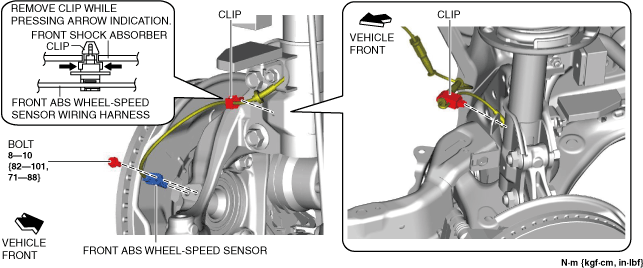
2. Disconnect the front ABS wheel-speed sensor wiring harness on the steering knuckle and set it aside so that it does not interfere with the servicing.
ac8wzw00002007
|
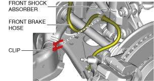
3. Remove the clip from the front shock absorber.
ac8wzw00002008
|
4. Remove the front brake hose from the front shock absorber.
5. Remove the locknut with the brake pedal depressed. (See Locknut Installation Note.)
ac8wzw00002009
|
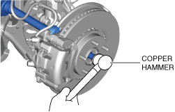
6. Temporarily install a spare nut to the front drive shaft.
7. Tap the nut with a copper hammer and separate the front drive shaft from the axle.
ac8wzw00002010
|
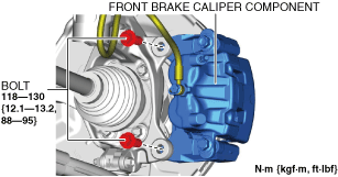
8. Remove the front brake caliper component installation bolts.
ac8wzw00002011
|
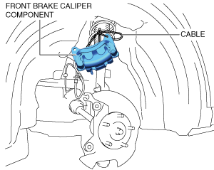
9. Remove the front brake caliper component and suspend it in a place out of the way using a cable.
ac8wzw00002012
|
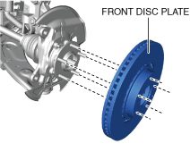
10. Remove the front disc plate.
ac8wzw00002013
|
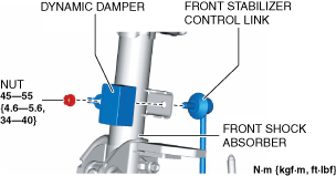
11. Remove the front stabilizer control link and dynamic damper from the front shock absorber.
ac8wzw00002014
|
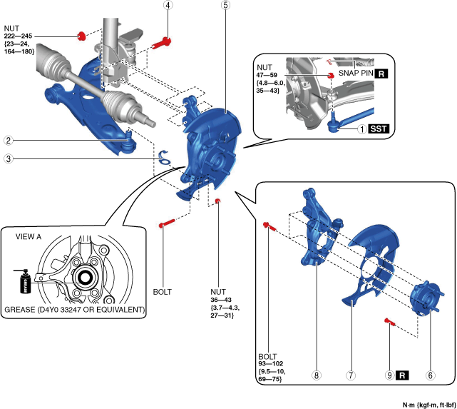
12. Remove in the order shown in the figure.
13. Install in the reverse order of removal.
14. When the steering knuckle is replaced, inspect the wheel alignment and adjust it if necessary. (See FRONT WHEEL ALIGNMENT.)
ac8wzw00004903
|
|
1
|
Tie-rod end
(See TIE-ROD END REPLACEMENT.)
|
|
2
|
Front lower arm ball joint
|
|
3
|
Spacer
|
|
4
|
Front shock absorber lower bolt
|
|
5
|
Front wheel hub, dust cover, steering knuckle component
|
|
6
|
Front wheel hub
|
|
7
|
Dust cover
|
|
8
|
Steering knuckle
|
|
9
|
Front wheel hub bolt
|
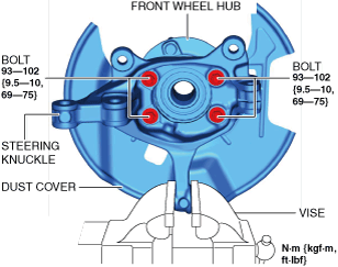
Front Wheel Hub, Dust Cover, and Steering Knuckle Removal Note
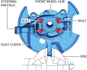
1. Secure the steering knuckle in a vise.
ac8wzw00002016
|
2. Remove the bolts and remove the front wheel hub and dust cover from the steering knuckle.
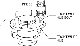
Front Wheel Hub Bolt Removal Note
1. Remove the front wheel hub bolt from the front wheel hub using a press.
ac8wzw00002017
|
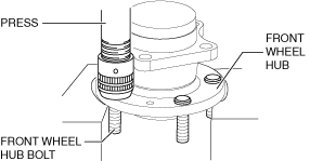
Front Wheel Hub Bolt Installation Note
1. Press fit the new front wheel hub bolt to the front wheel hub.
ac8wzw00004127
|
Front Wheel Hub, Dust Cover, and Steering Knuckle Installation Note
1. Secure the steering knuckle in a vise.
ac8wzw00002019
|
2. Install the dust cover and front wheel hub to the steering knuckle and tighten the bolts to the specified torque.
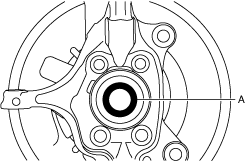
Front Wheel Hub, Dust Cover, and Steering Knuckle Component Installation Note
1. Apply grease (D4Y0 33247 or equivalent) to the wheel bearing inner race and front drive shaft contact surfaces (area A in the figure).
am3zzw00034658
|
2. Install the front wheel hub, dust cover, and steering knuckle component.
Front Shock Absorber Bolt Installation Note
1. Install the front shock absorber bolts in the directions indicated below and install the steering knuckle to the front shock absorber.
Locknut Installation Note
1. If dust or grease is on the drive shaft thread area, wipe it off with a cloth.
2. Tighten the locknut using the following procedure and with the brake pedal depressed.