 |
ac8jjw00000041
OIL COOLER REMOVAL/INSTALLATION [GW6A-EL, GW6AX-EL]
id0517i2117500
Replacement part
|
O-ring
Quantity: 2
Location of use: Oil cooler
|
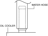
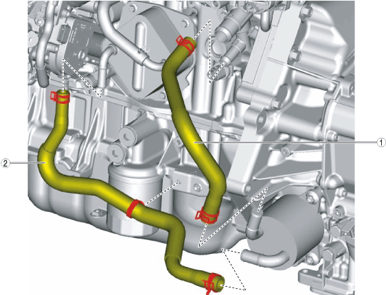
Water Hose
1. Set the coolant reserve tank aside with the hose connected. (See COOLANT RESERVE TANK REMOVAL/INSTALLATION [SKYACTIV-D 2.2].)
2. Remove front under cover No.2. (See FRONT UNDER COVER No.2 REMOVAL/INSTALLATION.)
3. Drain the engine coolant. (See ENGINE COOLANT REPLACEMENT [SKYACTIV-D 2.2].)
4. Remove using the procedure shown in the figure.
5. Install in the reverse order of removal.
6. Add engine coolant. (See ENGINE COOLANT REPLACEMENT [SKYACTIV-D 2.2].)
ac8jjw00000041
|
|
1
|
Water hose No.1
|
|
2
|
Water hose No.2
|
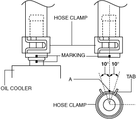
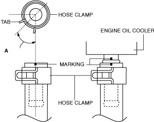
Water hose No.1/No.2 (oil cooler side) installation note
1. Install the water hose to the oil cooler as shown in the figure with the hose clamp expanded.
ac8wzw00001375
|
2. Install the hose clamp so that center A of the hose clamp tab is within the range shown in the figure.
Water hose No.1
ac8wzw00001376
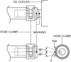
|
Water hose No.2
ac8wzw00001377
|
3. Verify that the hose clamp does not interfere with the surrounding engine accessories.
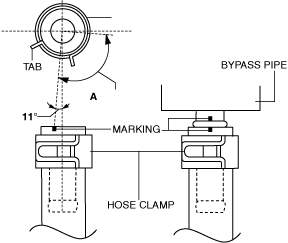
Water hose No.1 (bypass pipe side) installation note
1. Install the water hose to the bypass pipe as shown in the figure with the hose clamp expanded.
ac8wzw00001378
|
2. Install the hose clamp so that it is within the range of A shown in the figure.
ac8wzw00001379
|
3. Verify that the hose clamp does not interfere with the surrounding engine accessories.
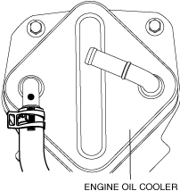
Water hose No.2 (engine oil cooler side) installation note
1. Install water hose No.2 to the engine oil cooler as shown in the figure with the hose clamp expanded.
ac8wzw00001380
|
2. Install the hose clamp so that it is within the range of A shown in the figure.
ac8wzw00001381
|
3. Verify that the hose clamp does not interfere with the surrounding engine accessories.
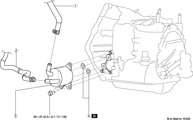
Oil cooler
1. Remove front under cover No.2. (See FRONT UNDER COVER No.2 REMOVAL/INSTALLATION.)
2. Drain the ATF. (See AUTOMATIC TRANSAXLE FLUID (ATF) REPLACEMENT [GW6A-EL, GW6AX-EL].)
3. Drain the engine coolant. (See ENGINE COOLANT REPLACEMENT [SKYACTIV-D 2.2].)
4. Remove using the procedure shown in the figure.
5. Install in the reverse order of removal.
6. Add engine coolant. (See ENGINE COOLANT REPLACEMENT [SKYACTIV-D 2.2].)
7. Add ATF. (See AUTOMATIC TRANSAXLE FLUID (ATF) REPLACEMENT [GW6A-EL, GW6AX-EL].)
8. Perform the mechanical system test. (See MECHANICAL SYSTEM TEST [GW6A-EL, GW6AX-EL].)
ac8wzw00001382
|
|
1
|
Water hose No.1
|
|
2
|
Water hose No.2
|
|
3
|
Oil cooler
|
|
4
|
O-ring
|
Water hose No.1/No.2 (oil cooler side) installation note
1. Install the water hose to the oil cooler as shown in the figure with the hose clamp expanded.
ac8wzw00001375
|
2. Install the hose clamp so that center A of the hose clamp tab is within the range shown in the figure.
Water hose No.1
ac8wzw00001376
|
Water hose No.2
ac8wzw00001377
|
3. Verify that the hose clamp does not interfere with the surrounding engine accessories.