 |
ac8wzn00001155
ON-BOARD DIAGNOSTIC SYSTEM [ELECTRIC POWER STEERING (EPS)]
id0602001009a1
Outline
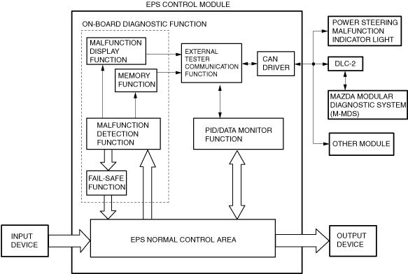
Block diagram
ac8wzn00001155
|
Function
Malfunction detection function
Malfunction display function
Memory function
DTC table
|
DTC |
Power steering malfunction indicator light illumination status |
Diagnosis system component |
Fail-safe |
Drive cycle |
Self test type*1 |
Memory function |
|---|---|---|---|---|---|---|
|
M-MDS |
||||||
|
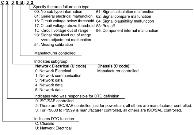
C200B:02
|
Illuminated/Indication
|
Torque sensor
|
×
|
—
|
C, D
|
×
|
|
C200B:16
|
Illuminated/Indication
|
Torque sensor
|
×
|
—
|
C, D
|
×
|
|
C200B:1C
|
Illuminated/Indication
|
Torque sensor
|
×
|
—
|
C, D
|
×
|
|
C200B:62
|
Illuminated/Indication
|
Torque sensor
|
×
|
—
|
C, D
|
×
|
|
C200B:64
|
Illuminated/Indication
|
Torque sensor
|
×
|
—
|
C, D
|
×
|
|
C200B:85
|
Illuminated/Indication
|
Torque sensor
|
×
|
—
|
C, D
|
×
|
|
C200C:1C
|
Illuminated/Indication
|
Torque sensor
|
×
|
—
|
C, D
|
×
|
|
C200D:1C
|
Illuminated/Indication
|
EPS motor
|
×
|
—
|
C, D
|
×
|
|
C200D:64
|
Illuminated/Indication
|
EPS motor
|
×
|
—
|
C, D
|
×
|
|
U0001:88
|
Illuminated/Indication
|
CAN system communication error
|
×
|
—
|
C, D
|
×
|
|
U0100:00
|
Illuminated/Indication
|
Communication error to PCM
|
×
|
—
|
C, D
|
×
|
|
U0121:00
|
—
|
Communication error to DSC HU/CM
|
×
|
—
|
C, D
|
×
|
|
U0126:00
|
—
|
Communication error to SAS control module
|
×
|
—
|
C, D
|
×
|
|
U0155:00
|
—
|
Communication error to instrument cluster
|
×
|
—
|
C, D
|
×
|
|
U0214:00
|
—
|
Communication error to start stop unit
|
×
|
—
|
C, D
|
×
|
|
U023A:00
|
—
|
Communication error to forward sensing camera (FSC)
|
×
|
—
|
C, D
|
×
|
|
U0338:00
|
—
|
Signal error from start stop unit
|
×
|
—
|
C, D
|
×
|
|
U0401:00
|
Vehicle speed signal error
• Illuminated/Indication
Engine speed signal error
• —
i-stop condition signal error
• —
|
Signal (vehicle speed) error from PCM
|
×
|
—
|
C, D
|
×
|
|
U0415:00
|
—
|
Signal error from DSC CM
|
×
|
—
|
C, D
|
×
|
|
U0423:00
|
—
|
Signal (engine switch status) error from instrument cluster
|
×
|
—
|
C, D
|
×
|
|
U0428:00
|
—
|
Signal error to SAS control module
|
×
|
—
|
C, D
|
×
|
|
U0515:00
|
—
|
Signal error from start stop unit
|
×
|
—
|
C, D
|
×
|
|
U053B:00
|
Illuminated/Indication
|
Signal error to forward sensing camera (FSC)
|
×
|
—
|
C, D
|
×
|
|
U053B:61
|
Illuminated/Indication
|
Forward sensing camera (FSC)
|
×
|
—
|
C, D
|
×
|
|
U053B:82
|
Illuminated/Indication
|
Signal error to forward sensing camera (FSC)
|
×
|
—
|
C, D
|
×
|
|
U053B:83
|
Illuminated/Indication
|
Signal error to forward sensing camera (FSC)
|
×
|
—
|
C, D
|
×
|
|
U2011:19
|
Illuminated/Indication
|
EPS motor
|
×
|
—
|
C, D
|
×
|
|
U2011:1C
|
Illuminated/Indication
|
EPS motor
|
×
|
—
|
C, D
|
×
|
|
U2011:62
|
Illuminated/Indication
|
EPS motor
|
×
|
—
|
C, D
|
×
|
|
U2011:72
|
Illuminated/Indication
|
EPS motor
|
×
|
—
|
C, D
|
×
|
|
U2011:92
|
Illuminated/Indication
|
EPS motor
|
×
|
—
|
C, D
|
×
|
|
U2300:54
|
—
|
EPS configuration
|
×
|
—
|
C, D
|
×
|
|
U2300:55
|
Illuminated/Indication
|
EPS configuration
|
×
|
—
|
C, D
|
×
|
|
U2300:56
|
—
|
EPS configuration
|
×
|
—
|
C, D
|
×
|
|
U3000:16
|
Illuminated/Indication
|
EPS CM
|
×
|
—
|
C, D
|
×
|
|
U3000:1C
|
Illuminated/Indication
|
EPS CM
|
×
|
—
|
C, D
|
×
|
|
U3000:28
|
Illuminated/Indication
|
EPS CM
|
×
|
—
|
C, D
|
×
|
|
U3000:41
|
Illuminated/Indication
|
EPS CM
|
×
|
—
|
C, D
|
×
|
|
U3000:46
|
—
|
EPS CM
|
×
|
—
|
C, D
|
×
|
|
U3000:47
|
Illuminated/Indication
|
EPS CM
|
×
|
—
|
C, D
|
×
|
|
U3000:49
|
Illuminated/Indication
|
EPS CM
|
×
|
—
|
C, D
|
×
|
|
U3000:4B
|
—
|
EPS CM
|
×
|
—
|
C, D
|
×
|
|
U3000:61
|
Illuminated/Indication
|
EPS CM
|
×
|
—
|
C, D
|
×
|
|
U3000:73
|
Illuminated/Indication
|
EPS CM
|
×
|
—
|
C, D
|
×
|
|
U3000:96
|
Illuminated/Indication
|
EPS CM
|
×
|
—
|
C, D
|
×
|
|
U3003:16
|
Illuminated/Indication
|
Battery power supply
|
×
|
—
|
C, D
|
×
|
|
U3003:17
|
Illuminated/Indication
|
Battery power supply
|
×
|
—
|
C, D
|
×
|
ac5wzn00004656
|
ac5wzn00004421
|
Fail-safe function
|
DTC |
Fail-safe control status |
|---|---|
|
M-MDS |
|
|
C200B:02
|
Control disabled
|
|
C200B:16
|
Control disabled
|
|
C200B:1C
|
Control is maintained in the backup control
|
|
C200B:62
|
Control disabled
|
|
C200B:64
|
Inhibits normal control, switches to backup control, and controls electric power steering so that steering assist can be maintained
|
|
C200B:85
|
Control disabled
|
|
C200C:1C
|
Control is maintained in the backup control
|
|
C200D:1C
|
Control is maintained in the backup control
|
|
C200D:64
|
Control disabled
|
|
U0001:88
|
Control enabled
|
|
U0100:00
|
Control is maintained in fail mode by gradually changing controlled vehicle speed
|
|
U0121:00
|
Control enabled
|
|
U0126:00
|
Control enabled
|
|
U0155:00
|
Control enabled
|
|
U0214:00
|
Control enabled
|
|
U023A:00
|
Control enabled
|
|
U0338:00
|
Control enabled
|
|
U0401:00
|
• Vehicle speed signal error
• Engine speed signal error
• i-stop condition signal error
|
|
U0415:00
|
Control enabled
|
|
U0423:00
|
• Control enabled
|
|
U0428:00
|
Control enabled
|
|
U0515:00
|
Control enabled
|
|
U053B:00
|
Control enabled
|
|
U053B:61
|
Control enabled
|
|
U053B:82
|
Control enabled
|
|
U053B:83
|
Control enabled
|
|
U2011:19
|
Control disabled
|
|
U2011:1C
|
Control disabled
|
|
U2011:62
|
Control disabled
|
|
U2011:72
|
• An open circuit malfunction is detected in the one phase of the three-phase stator in the EPS motor
• Other malfunction detected in EPS motor internal circuit
|
|
U2011:92
|
Control disabled
|
|
U2300:54
|
Control enabled
|
|
U2300:55
|
Control enabled
|
|
U2300:56
|
Control enabled
|
|
U3000:16
|
Control disabled
|
|
U3000:1C
|
Control disabled
|
|
U3000:28
|
Control disabled
|
|
U3000:41
|
Control disabled
|
|
U3000:46
|
Control is maintained in fail mode
|
|
U3000:47
|
Control disabled
|
|
U3000:49
|
Control disabled
|
|
U3000:4B
|
Control is maintained in fail mode
|
|
U3000:61
|
Control disabled
|
|
U3000:73
|
Control disabled
|
|
U3000:96
|
Control disabled
|
|
U3003:16
|
• Control is maintained by gradually decreasing the motor control current
|
|
U3003:17
|
Control disabled
|
Snapshot data table
|
Snapshot data item |
Unit |
Data contents |
Data read/use method |
Corresponding data monitor items |
|---|---|---|---|---|
|
AAT
|
°C, °F
|
Ambient air temperature
|
—
|
—
|
|
APP_STATUS
|
Accelerator Pedal Off/
Under 20%/
Over 20%/
FAIL
|
Accelerator pedal position
|
—
|
—
|
|
CEN_TRQ_S
|
Nm
|
Center value of torque sensor
|
—
|
CEN_TRQ_S
|
|
CFG_STATUS
|
Config Complete/
Not Configured/
Config Error
|
Instrument cluster configuration status
|
—
|
—
|
|
ECT_STATUS
|
Under 0 degrees C/
0 - Under 80 degrees C/
Over 80 degrees C/
FAIL
|
Engine coolant temperature status
|
—
|
—
|
|
ECU_IN_TMP
|
°C, °F
|
ECU internal temperature
|
—
|
ECU_IN_TMP
|
|
ENG_RPM
|
RPM
|
Engine speed
|
—
|
ENG_RPM
|
|
IC_VPWR
|
V
|
Instrument cluster power supply
|
• The EPS CM constantly receives the power supply voltage value of the instrument cluster sent via CAN signal from the instrument cluster.
• If a DTC is detected, the EPS CM records the power supply voltage of the instrument cluster when the DTC was detected, and it is displayed in the M-MDS.
|
VPWR*2
|
|
IG-ON_TIMER
|
hh:mm:ss*1
|
Elapsed time since ignition was switched ON
|
• The EPS CM constantly receives the elapsed time since the ignition was switched ON sent via CAN signal from the instrument cluster.
• If a DTC is detected, the EPS CM records the elapsed time since the ignition was switched ON when the DTC was detected, and it is displayed in the M-MDS.
|
—
|
|
LAS_CUR
|
A
|
Lane-keep assist system control output current
|
—
|
LAS_CUR
|
|
MT_CURRENT
|
A
|
Motor current
|
—
|
MT_CURRENT
|
|
OH_CR_C
|
No/Yes
|
Current overheat protection control (complete)
|
—
|
OH_CR_C
|
|
OH_CR_M
|
No/Yes
|
Current overheat protection control (middle)
|
—
|
OH_CR_M
|
|
OH_HIST_C
|
No/Yes
|
History of overheat protection control (complete)
|
—
|
OH_HIST_C
|
|
OH_HIST_M
|
No/Yes
|
History of overheat protection control (middle)
|
—
|
OH_HIST_M
|
|
OH_IG_CNT_C
|
—
|
The number of times the ignition is switched ON during the period from when overheat protection control (complete) is finished to the time the next overheat protection control (complete) is started
• Displays a maximum number of 255 times in which the ignition is switched ON until the first overheat protection control (complete) is started.
• During overheat protection control (complete), the number of times the ignition is switched ON is not counted, and 0 is displayed.
|
—
|
OH_IG_CNT_C
|
|
OH_IG_CNT_M
|
—
|
The number of times the ignition is switched ON during the period from when overheat protection control (middle) is finished to the time the next overheat protection control (middle) is started
• Displays a maximum number of 255 times in which the ignition is switched ON until the first overheat protection control (middle) is started.
• During overheat protection control (middle), the number of times the ignition is switched ON is not counted, and 0 is displayed.
|
—
|
OH_IG_CNT_M
|
|
PWR_MODE_KEY
|
Key Out/Key Recently Out (Position 0)/Accessory (Position 1)/Post Ignition (Position 2)/Ignition On (Position 2)/Running (Position 2)/Running - Starting
|
Power mode key state
|
• When a DTC is detected, the EPS CM receives the ignition switch condition being detected by the instrument cluster via CAN signals and displays it in the M-MDS.
|
—
|
|
RPM_STATUS
|
Engine Stop/
Under 1500rpm/
Over 1500rpm/
FAIL
|
Engine RPM status
|
• The EPS CM constantly receives the ignition switch status sent via CAN signal from the instrument cluster.
• If a DTC is detected, the EPS CM records the ignition switch status when the DTC was detected, and it is displayed in the M-MDS.
|
TACHOMTR*2
|
|
SHIFT_STATUS
|
P/N
D/
R/
FAIL
|
Shift position status
|
• The EPS CM constantly receives the selector lever position sent via CAN signal from the instrument cluster.
• If a DTC is detected, the EPS CM records the selector lever position when the DTC was detected, and it is displayed in the M-MDS.
|
Not applicable
|
|
STR_ANG
|
°
|
Steering wheel angle
|
—
|
STR_ANG
|
|
STR_ANG_EST
|
°
|
Steering wheel estimated absolute angle
|
—
|
STR_AB_EST
|
|
STR_ROT_SPD
|
°/s
|
Steering wheel rotation speed
|
—
|
STR_ROT_SPD
|
|
STR_TRQ_S_M
|
Nm
|
Steering shaft torque (Main)
|
—
|
STR_TRQ_S_M
|
|
STR_TRQ_S_S
|
Nm
|
Steering shaft torque (Sub)
|
—
|
STR_TRQ_S_S
|
|
TOTAL_DIST
|
km, ft, mi
|
Accumulated total traveled distance from completion of vehicle until EPS CM detects DTC (Odometer value in instrument cluster)
|
The distance traveled when the EPS CM detected a DTC can be calculated by performing the following procedure.
1. Verify the odometer value in the instrument cluster.
2. Verify the snap shot data item TOTAL_DIST.
3. Subtract 2 from 1.
|
—
|
|
TOTAL_TIME
|
hh:mm:ss*1
|
Accumulated total elapsed time since vehicle completion until EPS CM detects a DTC
|
The elapsed time when the EPS CM detected a DTC can be calculated by performing the following procedure.
1. Verify the PID item TOTAL_TIME of the instrument cluster.
2. Verify the snap shot data item TOTAL_TIME.
3. Subtract 2 from 1.
|
TOTAL_TIME*2
|
|
VPWR
|
V
|
Power supply
|
—
|
VPWR
|
|
VSPD
|
KPH, MPH
|
Vehicle speed
|
—
|
VSPD
|
|
VSPD_STATUS
|
Stop/
0 - 10 km/h/
Over 10 km/h/
FAIL
|
Vehicle speed status
|
• The EPS CM constantly receives the vehicle speed sent via CAN signal from the instrument cluster.
• If a DTC is detected, the EPS CM records the vehicle speed when the DTC was detected, and it is displayed in the M-MDS.
|
SPEEDOMTR*2
|
PID/data monitor function
PID/data monitor table
|
PID name (definition) |
Unit/Operation |
Operation Status (Reference) |
Inspection item(s) |
EPS control module terminal |
|---|---|---|---|---|
|
M-MDS display |
||||
|
CEN_TRQ_S
|
Nm
|
• Torque sensor neutral position: Near 0 Nm
|
• Steering column replacement
|
—
|
|
ECU_IN_TMP
|
°C, °F
|
• Displays temperature of board in EPS control module: -40°C—+215°C {-40°F—419°F}
|
• EPS CM replacement
|
—
|
|
LAS_CUR
|
A
|
• Lane-keep assist system is not operated: 0 A
• Steered: Changes to positive or negative
|
• EPS CM replacement
|
—
|
|
ENG_RPM
|
RPM
|
• Engine stopped: 0 RPM
• Engine rotating at 3,000 rpm: 3,000 RPM
|
• PCM inspection
|
—
|
|
MT_CURRENT
|
A
|
• When not steered: Near 0 A
• Steered: Changes to positive or negative
|
• EPS CM replacement
|
—
|
|
OH_CR_C
|
Yes/No
|
• Overheat protection control (complete) is operating: Yes
• Overheat protection control (complete) is not operating: No
|
—
|
—
|
|
OH_CR_M
|
Yes/No
|
• Overheat protection control (middle) is operating: Yes
• Overheat protection control (middle) is not operating: No
|
—
|
—
|
|
OH_HIST_C
|
Yes/No
|
• Before overheat protection control (complete) has operated: Yes
• Before overheat protection control (complete) has not operated: No
|
—
|
—
|
|
OH_HIST_M
|
Yes/No
|
• Before overheat protection control (middle) has operated: Yes
• Before overheat protection control (middle) has not operated: No
|
—
|
—
|
|
OH_IG_CNT_C
|
—
|
• The number of times the ignition is switched ON during the period from when overheat protection control (complete) is finished to the time the next overheat protection control (complete) is started
|
—
|
—
|
|
OH_IG_CNT_M
|
—
|
• The number of times the ignition is switched ON during the period from when overheat protection control (middle) is finished to the time the next overheat protection control (middle) is started
|
—
|
—
|
|
STR_AB_EST
|
°
|
• Steering wheel in neutral position (not turned): 0°
• Steered left: Changes to 0°—Positive
• Steered right: Changes to 0°—Negative
|
Perform the DTC inspection for the PCM, DSC HU/CM, and EPS CM.
If a DTC is displayed after performing the DTC inspection for the PCM, DSC HU/CM, and EPS CM, repair the malfunctioning part according to the applicable DTC troubleshooting.
After performing the DTC inspection, perform the following procedures:
• Switch the ignition off and maintain condition for approx. 3 s.
• Set the vehicle wheels straight-ahead.
• Switch the ignition ON (engine off or on).
If an abnormal value is indicated after verifying the value of the STR_ANG again, replace the EPS CM.
|
—
|
|
STR_ANG
|
°
|
• Steering wheel position when ignition is switched ON (engine off or on): 0°
• Steered left: Changes to 0°—Positive
• Steered right: Changes to 0°—Negative
|
—
|
|
|
STR_ROT_SPD
|
°/s
|
• Not steered: Near 0 °/s
• Steered: Changes according to steering speed
|
• EPS CM replacement
|
—
|
|
STR_TRQ_S_M
|
Nm
|
• Not steered: Near 0 Nm
• Steered left: Changes to 0 Nm—Positive
• Steered right: Changes to 0 Nm—Negative
|
• EPS CM replacement
|
—
|
|
STR_TRQ_S_S
|
Nm
|
• Not steered: Near 0 Nm
• Steered left: Changes to 0 Nm—Positive
• Steered right: Changes to 0 Nm—Negative
|
• EPS CM replacement
|
—
|
|
VPWR
|
V
|
• Engine stopped: Approx. 12 V
• Idling: Approx. 14 V
|
• Battery inspection
• Power supply circuit inspection (ignition switch, fuses)
|
1B
|
|
VSPD
|
KPH, MPH
|
• Vehicle stopped: 0 KPH, 0 MPH
• Vehicle speed 20 km/h {12 mph}: 20 KPH, 12 MPH
|
• PCM inspection
|
—
|
|
YAW_RATE
|
Deg/Sec
|
• Vehicle stopped: 0 °/s
|
• EPS control module inspection
• Forward sensing camera inspection
|
—
|
External tester communication function
Connections/Communication Contents
|
External tester |
||
|---|---|---|
|
Mazda modular diagnostic system (M-MDS) |
||
|
Connection |
Communication method |
|
|
On-board diagnostic (malfunction detection) function
|
Input/output: CAN_H (HS), CAN_L (HS)
|
Serial communication
|
|
PID/DATA monitor function
|
Input/output: CAN_H (HS), CAN_L (HS)
|
Serial communication
|
|
Diagnostic function name |
Signal received |
Signal sent |
|---|---|---|
|
Malfunction detection function
|
DTC verification signal
|
Diagnostic trouble code
|
|
PID/DATA monitor function
|
Command signal to read selected monitor item
|
Monitored data for requested monitor item
|