 |
ac8wzn00001111
ELECTRIC POWER STEERING SYSTEM
id061300245900
Outline
Purpose, Function
Construction
|
Part name |
Functions |
|---|---|
|
EPS CM
|
• Calculates the optimum assist force based on the signals from the torque sensor, EPS motor, PCM, DSC HU/CM, and SAS control module, and outputs the EPS motor drive current.
• After the vehicle begins moving, the system performs self-learning of the steering angle neutral position based on the signals from the DSC HU/CM and the SAS control module, and outputs it as a steering angle (estimated absolute steering angle) signal to CAN.
• Outputs an power steering malfunction indication on/flash request signal and a power steering warning buzzer request signal to CAN when there is a malfunction in the EPS system.
|
|
PCM
|
• Transmits a vehicle speed signal, engine speed signal, and i-stop condition signal to the EPS CM via CAN communication.
|
|
DSC HU/CM
|
• Transmits a vehicle wheel speed signal to the EPS CM via CAN communication.
|
|
Start stop unit
|
• Transmits the signal from the steering angle sensor to the EPS CM as a steering angle (absolute steering angle) signal via CAN communication.
|
|
SAS control module
|
• Transmits the vehicle lateral-G (vehicle lateral acceleration speed) and yaw rate (vehicle turning angle speed) to the EPS CM via CAN communication.
|
|
Instrument cluster
|
• Turns on/flashes the power steering malfunction indication based on the power steering malfunction indication on/flash request signal and power steering warning buzzer request signal output by the EPS CM, and activates the power steering warning buzzer to alert the driver that there is a malfunction the EPS system.
|
Structural View
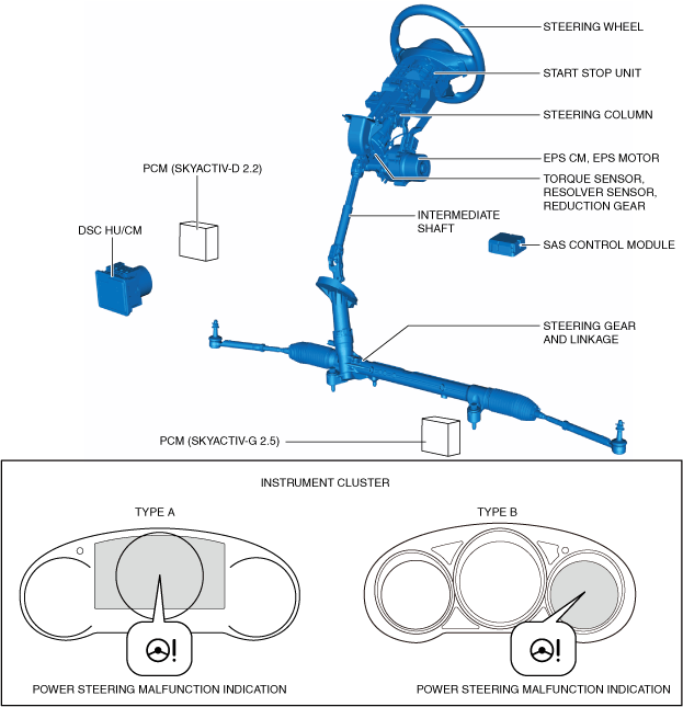
L.H.D.
ac8wzn00001111
|
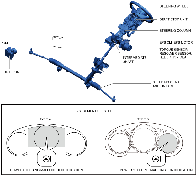
R.H.D.
ac8wzn00001194
|
System Wiring Diagram
ac8wzn00000816
|
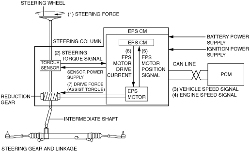
Operation
1. Steering force (1) generated by the driver's steering wheel operation is detected by the torque sensor built into the steering column and shaft, and it is output (2) to the EPS CM as a steering torque signal.
2. The EPS CM calculates optimum assist force based on the steering torque signal (2) from the torque sensor and the vehicle speed signal (3) and engine speed signal (4) from the PCM, and EPS motor position information (5) from the EPS motor, and outputs (6) electric current to drive the EPS motor.
3. The EPS motor drive force (assist torque) generated by the EPS motor drive current (6) from the EPS CM is transmitted (7) to the intermediate shaft via the reduction gear to assist the driver's steering operation.
ac8wzn00000282
|