 |
ac8wzn00000778
REAR WIPER/WASHER SYSTEM
id091900002000
Outline
Function
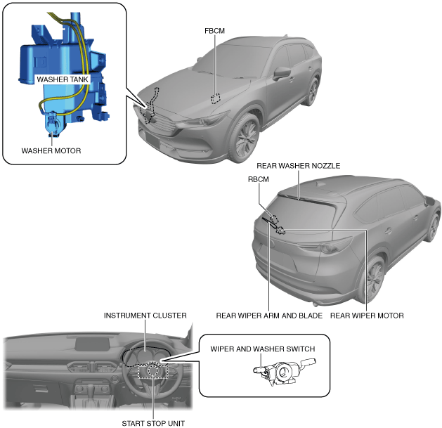
Structure/Construction
System structure
ac8wzn00000778
|
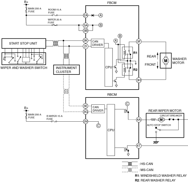
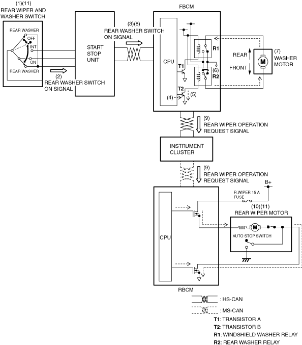
System wiring diagram
ac8wzn00000779
|
Operation
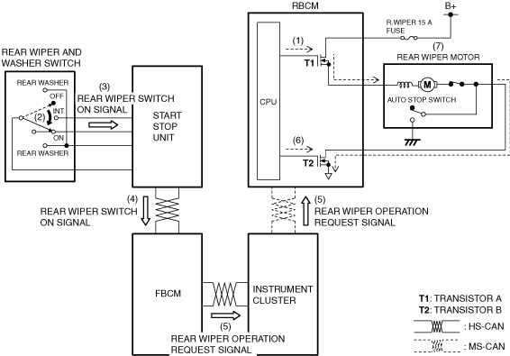
Continuous wiper operation
1. When the ignition is switched ON (engine off or on), the rear body control module (RBCM) turns (1) transistor A on.
2. When the rear wiper and washer switch is in the ON position (2), the start stop unit detects (3) the rear wiper switch ON signal.
3. When the start stop unit detects the rear wiper switch ON signal, the rear wiper switch ON signal is sent (4) to the front body control module (FBCM) by CAN communication.
4. When the front body control module (FBCM) receives a rear wiper switch on signal, it sends (5) a rear wiper operation request signal to the rear body control module (RBCM) via the instrument cluster as a CAN signal.
5. When the rear body control module (RBCM) receives the rear wiper operation request signal, it turns (6) transistor B on.
6. When transistors B turn on, the rear wiper operates (7) continuously.
ac5uun00002651
|
Auto-stop operation
ac8wzn00000780
|
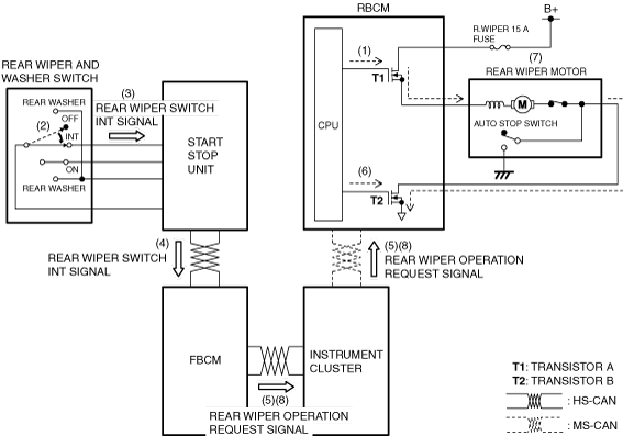
Intermittent wiper operation
1. When the ignition is switched ON (engine off or on), the rear body control module (RBCM) turns (1) transistor A on.
2. When the rear wiper and washer switch is in the INT position (2), the start stop unit detects (3) the rear wiper switch INT signal.
3. When the start stop unit detects the rear wiper switch INT signal, the rear wiper switch INT signal is sent (4) to the front body control module (FBCM) by CAN communication.
4. When the front body control module (FBCM) receives a rear wiper switch INT signal, it sends (5) a rear wiper operation request signal to the rear body control module (RBCM) via the instrument cluster as a CAN signal.
5. When the rear body control module (RBCM) receives the rear wiper operation request signal, it turns (6) transistor B on.
6. When transistors B turn on, the rear wiper operates (7).
7. The front body control module (FBCM) sends (8) a rear wiper operation request signal to the rear body control module (RBCM) via the instrument cluster at regular intervals. Due to this, the rear wiper operates intermittently.
ac5uun00002653
|
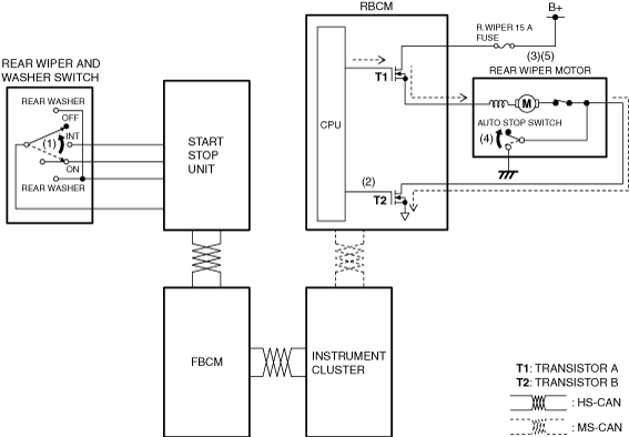
Synchronized washer operation
1. When the rear wiper and washer switch is in the rear washer position (1) with the ignition switched ON (engine off or on), the start stop unit detects (2) the rear washer switch on signal.
2. The start stop unit sends (3) the rear washer switch on signal to the front body control module (FBCM) via CAN communication.
3. When the front body control module (FBCM) receives the rear washer switch on signal, it turns transistor B on (4).
4. When transistor B turns on, a ground circuit with the rear washer relay is established (5), and the rear washer relay turns on (6).
5. When the rear washer relay turns on, the washer motor is driven (7) and washer fluid is sprayed from the rear washer nozzle.
6. When the front body control module (FBCM) receives (8) the rear washer switch on signal for a certain period of time, it sends (9) a rear wiper operation request signal to the rear body control module (RBCM) via the instrument cluster as a CAN signal.
7. When the rear body control module (RBCM) receives the rear wiper operation request signal, it operates (10) the rear wiper.
8. When the rear washer switch is turned off, the rear wiper stops (11) after it operates for approx. 2.6 s.
ac5uun00002654
|