PARKING ASSIST SYSTEM
id092000014000
Outline
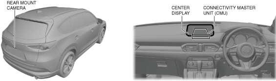
• When the vehicle is reversing, images at the rear of the vehicle shot by the rear mount camera located on the liftgate garnish are displayed in the center display to aid the driver in verifying the presence of pedestrians and obstructions at the rear of the vehicle.
Functions
Rear view monitor display function
• When the CMU receives a video signal from the rear mount camera, it displays the distance reference lines and vehicle width extension lines on the image at the rear of the vehicle shot by the rear mount camera in the center display.
Structural view
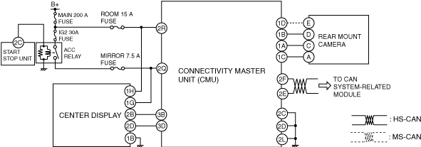
System wiring diagram
Image range
Rear mount camera
• The rear mount camera shoots images in the range shown in the figure.
-
Note
-
• The image range may differ depending on the road surface conditions and the vehicle conditions. In addition, the rear mount camera cannot shoot images near both sides of the rear bumper and below the rear bumper.
Rear view monitor display
|
Display item
|
Display line color
|
Content
|
|
Distance reference lines (fixed)
|
Red
|
• Shows distance reference line 0.5 m {20 in} from the rear of the rear bumper.
• Not in conjunction with steering operation.
|
|
Yellow
|
• Shows distance reference line 1.0 m {39 in} from the rear of the rear bumper.
• Not in conjunction with steering operation.
|
|
Yellow
|
• Shows distance reference line 2.0 m {79 in} from the rear of the rear bumper.
• Not in conjunction with steering operation.
|
|
Vehicle width extension line
|
Yellow
|
• Vehicle width extension line.
|
|
Parking sensor detection display
|
—
|
• Icon for indicating detection/non-detection of the parking sensor. (With parking sensor system)
|
Operation
-
Note
-
• Under the following conditions, images captured by the rear mount camera may be difficult to see, however this does not indicate a malfunction.
-
― Light from the sun or a vehicle's headlights is reflected off the lens
― The image area is dark due to low light levels such as in the evening
― The temperature around the lens increases or decreases
― Water droplets, snow, or mud is on the lens
Guide line display
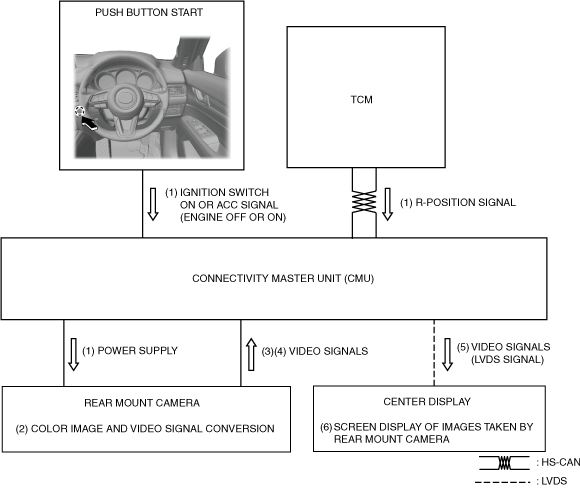
1. When the ignition is switched to ACC or ON (engine off or on) and an R position signal from the selector lever is received (1), the CMU supplies (1) power to the rear mount camera.
2. The rear mount camera shoots the conditions at the rear of the vehicle in color which is converted (2) to a video signal.
3. The rear mount camera combines the distance reference lines (fixed lines) and the vehicle width extension lines with the camera images and converts (3) them to a video signal.
4. The rear mount camera sends (4) the converted video signal to the connectivity master unit (CMU).
5. When a video signal is received from the rear mount camera, the CMU sends the received (5) video signal (LVDS signal) to the center display.
6. The center display displays (6) the images at the rear of the vehicle taken by the rear mount camera based on the received video signal (LVDS signal).