ON-BOARD DIAGNOSTIC [ACTIVE DRIVING DISPLAY]
id092200021858
Outline
• The on-board diagnostic function consists of the following functions:
-
― A malfunction detection function, which detects overall malfunctions in the instrument cluster-related parts.
― A memory function, which stores detected DTCs.
― A display function, which indicates malfunction locations and status via DTC output.
― A PID/data monitoring function, which reads out specific input/output signals and verifies the input/output condition.
• Using the Mazda Modular Diagnostic System (M-MDS), DTCs can be read out and deleted, and the PID/data monitoring function can be activated.
Malfunction detection function
• Detects malfunctions in input/output signals.
• If a malfunction occurs, the active driving display records the malfunction as a DTC. A recorded DTC can be read by the Mazda Modular Diagnostic System (M-MDS).
×: Applicable
—: Not applicable
|
DTC No.
|
Warning/indicator light
|
Description
|
Fail-safe
|
Drive cycle
|
Self test type*1
|
Memory function
|
|
U0001:88
|
—
|
Module communication error (HS-CAN)
|
—
|
—
|
C
|
×
|
|
U3000:41
|
—
|
Active driving display internal malfunction
|
—
|
—
|
C
|
×
|
|
U3003:16
|
—
|
Low power supply voltage input to active driving display
|
—
|
—
|
C
|
×
|
*1 :C: CMDTC self test, D: ODDTC self test
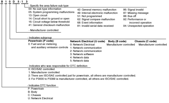
DTC 7-digit code definition
-
• When related systems or components have failed, the CM stores the DTC of the malfunctioning part in the CM memory, and allows for the retrieval of the store data using scanning tool when necessary. The DTCs are indicated using seven digits. Each digit indicates the following.
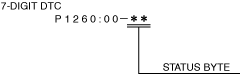
Status byte for DTC
-
• The two digits (two digits after hyphen (-)) after the 7-digit DTC.
• A code which indicates the pending code, current/past malfunction status, or warning illumination status.
• Can be read by performing a CMDTC self-test using the Mazda Modular Diagnostic System (M-MDS).
• For details on the status byte, refer to the explanation on the Mazda Modular Diagnostic System (M-MDS) when reading the DTC.
Detection condition for the applicable DTC
|
DTC No.
|
Description
|
Detection condition
|
|
U0001:88
|
Module communication error (HS-CAN)
|
• Active driving display detects a CAN bus communication line (HS-CAN) malfunction.
|
|
U3000:41
|
Active driving display internal malfunction
|
• With the ignition switched ON (engine off or on), a malfunction in the active driving display is detected.
|
|
U3003:16
|
Low power supply voltage input to active driving display
|
• Active driving display power supply circuit voltage of less than 10 V is detected for 5 s or more with the ignition switched ON (engine off or on).
|
Snapshot Data
-
Note
-
• The active driving display stores the following two types of snapshot data (vehicle information) when a DTC is detected and displays them in the Mazda Modular Diagnostic System (M-MDS).
-
― Vehicle information detected by active driving display
― Vehicle information detected by instrument cluster and received by active driving display via CAN communication
• The data for all DTCs currently detected is stored.
—: Not applicable
|
Snapshot data item
|
Unit
|
Data contents
|
Data read/use method
|
Corresponding data monitor items
|
|
AAT
|
°C
|
°F
|
Ambient temperature
|
—
|
—
|
|
APP_STATUS
|
Accelerator Pedal Off/Under20%/Over20%/FAIL
|
Accelerator pedal position status
|
—
|
—
|
|
CFG_STATUS
|
Config Complete/Not Configured/Config Error
|
Instrument cluster configuration status
|
—
|
—
|
|
ECT_STATUS
|
Under 0 degrees C/0 - Under 80 degrees C/Over 80 degrees C/FAIL
|
Engine coolant temperature status
|
—
|
—
|
|
IG-ON_TIMER
|
hh:mm:ss*2
|
Elapsed time since ignition was switched ON (engine off or on)
-
Note
-
• The instrument cluster records the elapsed time since the ignition was switched ON (engine off or on).
|
• The active driving display constantly receives the elapsed time since the ignition was switched ON (engine off or on) sent via CAN signal from the instrument cluster.
• If a DTC is detected, the active driving display records the elapsed time since the ignition was switched ON (engine off or on) when the DTC was detected, and it is displayed in the M-MDS.
|
—
|
|
PWR_MODE_KEY
|
Key Out/Key Recently Out (Position 0)/Accessory (Position 1)/Post Ignition (Position 2)/Ignition On (Position 2)/Running (Position 2)/Running - Starting
|
• Key Out: Ignition switched off
• Key Recently Out (Position 0): Elapsed time within 3 s since ignition was switched off
• Accessory (Position 1): Ignition is switched to ACC
• Post Ignition (Position 2): Elapsed time within 3 s since ignition was switched ON (engine off or on)
• Ignition On (Position 2): Ignition switched ON (engine off)
• Running (Position 2): Ignition switched ON (engine on)
• Running - Starting: Cranking condition
|
• The active driving display constantly receives the ignition switch status sent via CAN signal from the instrument cluster.
• If a DTC is detected, the active driving display records the ignition switch status when the DTC was detected, and it is displayed in the M-MDS.
|
—
|
|
RPM_STATUS
|
Engine Stop/Under1500rpm/Over1500rpm/FAIL
|
Engine speed status
|
• The active driving display constantly receives the engine speed sent via CAN signal from the instrument cluster.
• If a DTC is detected, the active driving display records the engine speed when the DTC was detected, and it is displayed in the M-MDS.
|
TACHOMTR*1
|
|
SHIFT_STATUS
|
P/N/
D/
R/
FAIL
|
Selector lever position status
|
• The active driving display constantly receives the selector lever position sent via CAN signal from the instrument cluster.
• If a DTC is detected, the active driving display records the selector lever position when the DTC was detected, and it is displayed in the M-MDS.
|
—
|
|
TOTAL_DIST
|
km
|
Miles
|
Accumulated total traveled distance from completion of vehicle until active driving display detects DTC (Odometer value in instrument cluster)
|
The total traveled distance from which the active driving display detects DTCs to the present can be calculated by performing the following procedure.
1. Verify the odometer value in the instrument cluster.
2. Verify the snapshot data item TOTAL_DIST.
3. Subtract 2 from 1.
|
—
|
|
TOTAL_TIME
|
hh:mm:ss*2
|
Accumulated total elapsed time since vehicle completion until active driving display detects a DTC
-
Note
-
• When the ROOM fuse is removed, and the ignition is switched off, the time is not included in the elapsed time.
|
The elapsed time from which the active driving display detects DTCs to the present can be calculated by performing the following procedure.
1. Verify the instrument cluster PID item TOTAL_TIME.
2. Verify the snapshot data item TOTAL_TIME.
3. Subtract 2 from 1.
|
TOTAL_TIME*1
|
|
VPWR
|
V
|
Active driving display power supply voltage
|
—
|
VPWR_B
|
|
VSPD_STATUS
|
Stop/0-10km/h/Over10km/h/FAIL
|
Vehicle speed status
|
• The active driving display constantly receives the vehicle speed sent via CAN signal from the instrument cluster.
• If a DTC is detected, the active driving display records the vehicle speed when the DTC was detected, and it is displayed in the M-MDS.
|
—
|
*2 :The seconds may be indicated after the decimal point.
Data Monitor Function
• With the PID/data monitor function, the input/output signal monitor items set in the instrument cluster can be selected and read out in real-time.
• The items which can be selected are as follows.
—: Not applicable
|
PID
|
Unit/Operation
|
Data contents
|
Module control terminal
|
|
VPWR_B
|
V
|
Displays active driving display power supply voltage.
|
• A, B, E
|
Simulation function
• The simulation function drives the output parts set in the instrument cluster regardless of the instrument cluster control condition.
• The items which can be selected are as follows.
-
Note
-
• Simulation items on parts which are not equipped to the vehicle do not operate.
|
Simulation item
|
Unit/Operation
|
Data contents
|
Output part name
|
|
HUD_TEST
|
Off/On
|
• Off: Turn off the demonstration function of the active driving display.
• On: Turn on the demonstration function of the active driving display.
|
Active driving display
|