ac5wzn00004178
|
MULTIPLEX COMMUNICATION SYSTEM
id100000001400
Outline
ac5wzn00004178
|
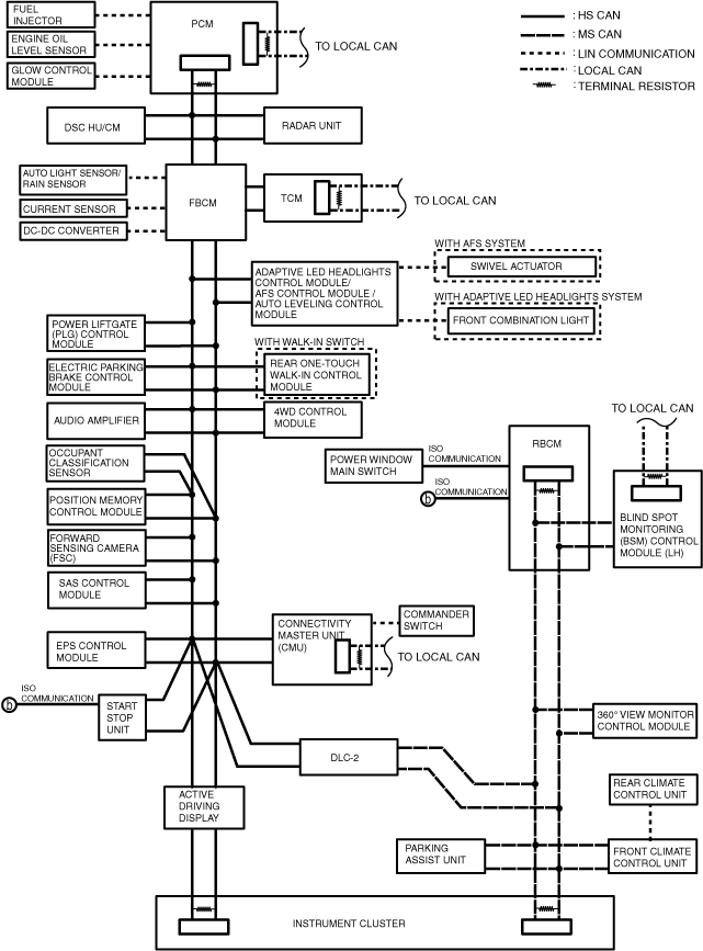
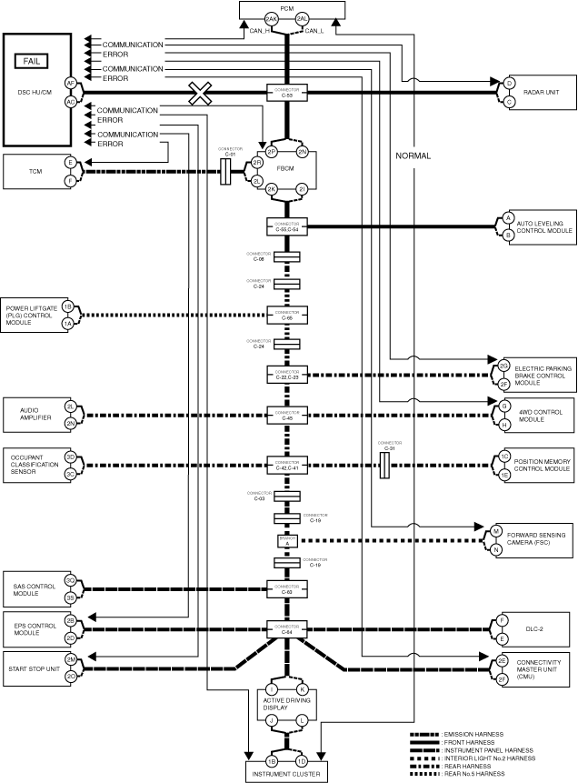
System Wiring Diagram
ac8wzn00000648
|
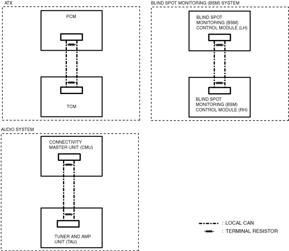
Local CAN
ac8wzn00000649
|
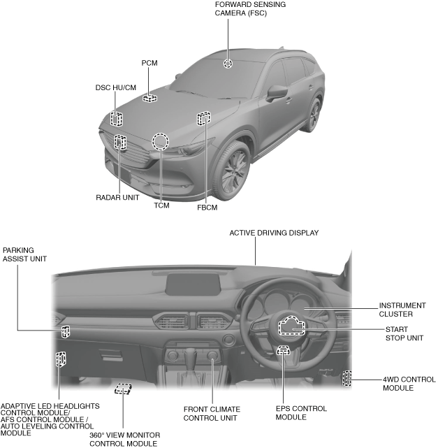
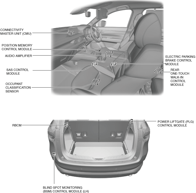
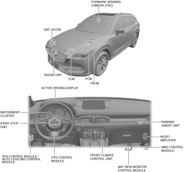
Structural View
R.H.D.
ac8wzn00000650
|
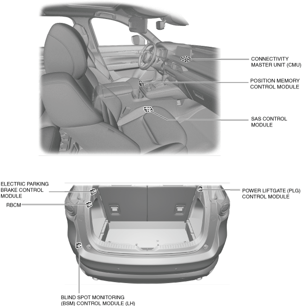
ac8wzn00000651
|
L.H.D.
ac8ccn00000194
|
ac8wzn00001011
|
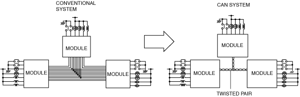
Function
CAN (controller area network) system
Malfunction diagnosis procedure
Ex.) Open circuit location determination procedure
1. Verify the CAN system-related module DTCs and the failed module using the Mazda Modular Diagnostic System (M-MDS).
|
DTC output module |
Mazda Modular Diagnostic System (M-MDS) display |
Output DTC |
|---|---|---|
|
PCM
|
PCM
|
U0121:00
|
|
Radar unit
|
SBS/MRCC
|
U0121:00
|
|
TCM
|
TCM
|
U0121:00
|
|
FBCM
|
F_BCM
|
U0121:00
|
|
Electric parking brake control module
|
EPB
|
U0121:00
|
|
4WD control module
|
4X4
|
U0121:00
|
|
Forward sensing camera (FSC)
|
FSC
|
U0121:00
|
|
Start stop unit
|
SSU
|
U0121:00
|
|
U0121:87
|
||
|
Connectivity master unit (CMU)
|
CMU
|
U0121:00
|
|
EPS control module
|
EPS
|
U0121:00
|
|
Instrument cluster
|
IC
|
U0121:00
|
|
Module |
Fail display |
|---|---|
|
DSC HU/CM
|
×
|
2. As a result of DTC verification, only DTCs related to DSC HU/CM and communication errors are output and the DSC HU/CM is indicated as failed, therefore there could be a malfunction in the DSC HU/CM or in the wiring harness between connector C-53 and DSC HU/CM.
ac8wzn00000652
|
Local CAN
LIN communication
ISO communication
Construction
CAN
Local CAN
LIN communication
ISO communication