 |
ac5wzw00011263
COOLING FAN MOTOR INSPECTION [SKYACTIV-G 2.5]
id0112h5801800
Cooling fan control system Inspection
1. Connect the M-MDS to the DLC-2.
2. Perform the KOEO or KOER self-test using the M-MDS and verify that none of the following DTCs isdetected. (See DTC INSPECTION.)
3. Verify that the engine coolant temperature is less than 97°C {206°F}, and then start the engine and idle it.
4. Verify that the cooling fan does not operate when the A/C switch is turned off.
|
Cooling fan status |
Inspection items |
|
|---|---|---|
|
Cooling fan No.1 |
Cooling fan No.2 |
|
|
Low
|
Low
|
• Cooling fan relay No.2 (stuck closed))
|
|
High
|
High
|
• A/C pressure sensor
• Climate control unit
• CAN communication (PID: AC_REQ constantly ON)
|
|
Off
|
High
|
• Cooling fan relay No.3 (stuck closed)
|
5. When FAN1 is turned from off to on using the M-MDS simulation function, verify that cooling fans No.1, and 2 operate at low speed.
|
Cooling fan status |
Inspection items |
|
|---|---|---|
|
Cooling fan No.1 |
Cooling fan No.2 |
|
|
Off
|
Off
|
• Cooling fan relay No.2 (stuck closed)
• Cooling fan No.1 (internal open circuit)
• Cooling fan No.2 (internal open circuit)
• Wiring harnesses between battery and cooling fan relay No.2 and cooling fan No.1 (fuse blown due to open circuit and short to ground)
• Wiring harnesses between cooling fan No.1 and cooling fan relay No.3 and cooling fan No.2 (open circuit)
• Wiring harness between cooling fan No.2 and ground (open circuit and poor ground)
|
|
High
|
Off
|
• Cooling fan relay No.1 (stuck closed)
• Wiring harnesses between cooling fan No.1 and cooling fan relay No.3 and cooling fan No.2 (short to ground)*
|
6. When FAN1 and FAN3 are turned from off to on using the M-MDS simulation function, verify that cooling fans No.1 and 2 operate at high speed.
|
Cooling fan status |
Inspection items |
|
|---|---|---|
|
Cooling fan No.1 |
Cooling fan No.2 |
|
|
Off
|
High
|
• Cooling fan relay No.1 (stuck open)
• Wiring harness between cooling fan relay No.1 and ground (open circuit and poor ground)
|
|
High
|
Off
|
• Cooling fan relay No.3 (stuck open)
• Wiring harness between battery and cooling fan relay No.3 (fuse blown due to open circuit and short to ground)
|
Part Inspection
1. Verify that the battery is fully charged. (See BATTERY INSPECTION.)
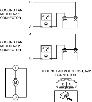
2. Disconnect the cooling fan motor connector (2 terminals).
3. Install a tester and battery to the cooling fan motor connector (2 terminals) as shown in the figure.
ac5wzw00011263
|
4. Verify that each cooling fan motor operates smoothly at the standard current.