 |
ac5wzw00005108
SIDE CAMERA INSPECTION
id152000009300
Type-A
1. Disconnect the negative battery terminal. (See NEGATIVE BATTERY TERMINAL DISCONNECTION/CONNECTION.)
2. Remove the following parts:
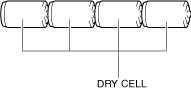
3. Prepare four dry cell batteries (1.5 V)
4. Connect the four dry cell batteries in a series.
ac5wzw00005108
|
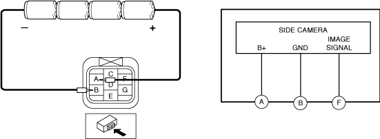
5. Connect the positive pole of the dry cell battery to side camera terminal A, and the negative pole to terminal B.
ac8wzw00004546
|
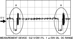
6. With the cell batteries being connected, measure the waveform between side camera terminal F and terminal B.
7. Verify that waveform A shown in the figure is displayed two times or more.
ac5wzw00010254
|
Type-B
1. Connect the M-MDS to the DLC-2.
2. Perform the DTC inspection for the 360° view monitor control module and verify if any DTCs related to the side camera is detected. (See DTC INSPECTION [360°VIEW MONITOR CONTROL MODULE (TYPE-B)].)