49 E011 1A0
Ring gear brake set
49 S033 101
Dust cover installer

—
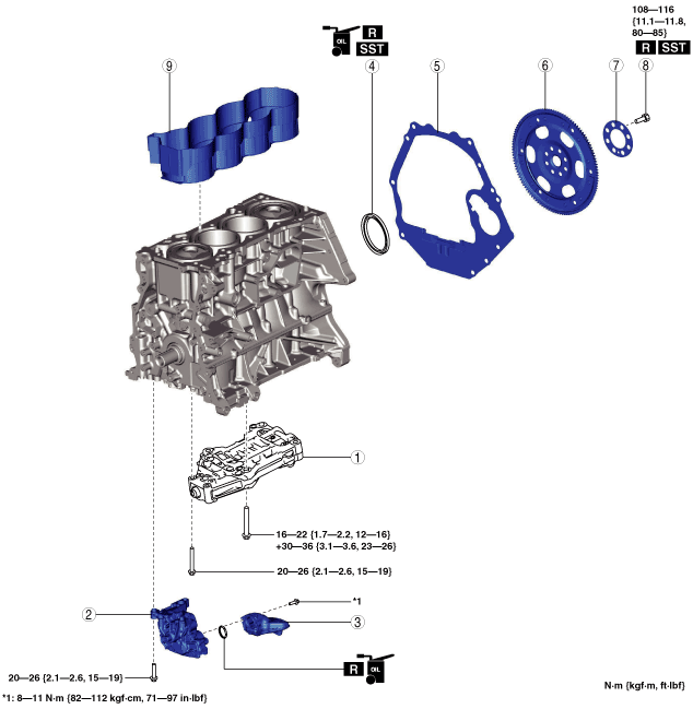
CYLINDER BLOCK ASSEMBLY (II)
id011000504100
Special Service Tool (SST)
|
49 E011 1A0
Ring gear brake set
|
|
49 S033 101
Dust cover installer
|
|
—
|
1. Assemble in the order indicated in the table.
bp25ue00000024
|
|
1
|
Balancer unit
(See Balancer Unit Assembly Note.)
|
|
2
|
Oil pump
(See Oil Pump Assembly Note.)
|
|
3
|
Oil strainer
|
|
4
|
Rear oil seal
(See Rear Oil Seal Assembly Note.)
|
|
5
|
End plate
(See End Plate Assembly Note.)
|
|
6
|
Drive plate
|
|
7
|
Backing plate
|
|
8
|
Drive plate installation bolt
|
|
9
|
Water jacket spacer
|
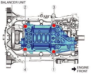
Balancer Unit Assembly Note
1. Assemble the balancer unit using the following procedure:
bp25ue00000025
|
Tightening torque
|
Installation position |
Tightening torque |
|---|---|
|
1—4
|
16—22 N·m {1.7—2.2 kgf·m, 12—16 ft·lbf}
|
|
5, 6
|
20—26 N·m {2.1—2.6 kgf·m, 15—19 ft·lbf}
|
bp25ue00000026
|
Oil Pump Assembly Note
1. Install the oil pump using the following procedure:
bp25ue00000027
|
bp25ue00000028
|
bp25ue00000029
|
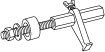
Rear Oil Seal Assembly Note
1. Apply clean engine oil to the inner surface of a new rear oil seal.
2. Insert the rear oil seal into the cylinder block by hand.
3. Tap the oil seal in evenly using the SST and a hammer.
bp25ue00000030
|
bp25ue00000031
|
End Plate Assembly Note
1. After end plate assembly, crimp the parts A and B shown in the figure.
bp26ze00000011
|
2. After crimping, verify that there is no damage and removal of the end plate.
Drive Plate Installation Bolt Assembly Note
1. Hold the crankshaft using the SST.
2. Tighten the new bolts in two or three passes in the order shown in the figure.
bp26ze00000012
|