CYLINDER HEAD ASSEMBLY (II)
id011000504400
-
Caution
-
• If the camshaft is rotated with the timing chain removed and the piston at the top dead center position, the valve may contact the piston and the engine could be damaged. When rotating the camshaft with the timing chain removed, rotate it after lowering the piston from the top dead center position.
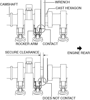
• When rotating the camshaft using a wrench on the cast hexagon, the wrench may contact the rocker arm and damage the rocker arm. To prevent damage to the rocker arm when holding the camshaft on the cast hexagon, use a wrench on the rear side of the engine as shown in the figure to secure a clearance between the cam.
• Carefully assemble the HLA because the specification is different between the intake side and the exhaust side.
-
Note
-
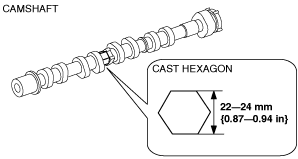
• Width at the cast hexagon of the camshaft is 22—24 mm {0.87—0.94 in}.
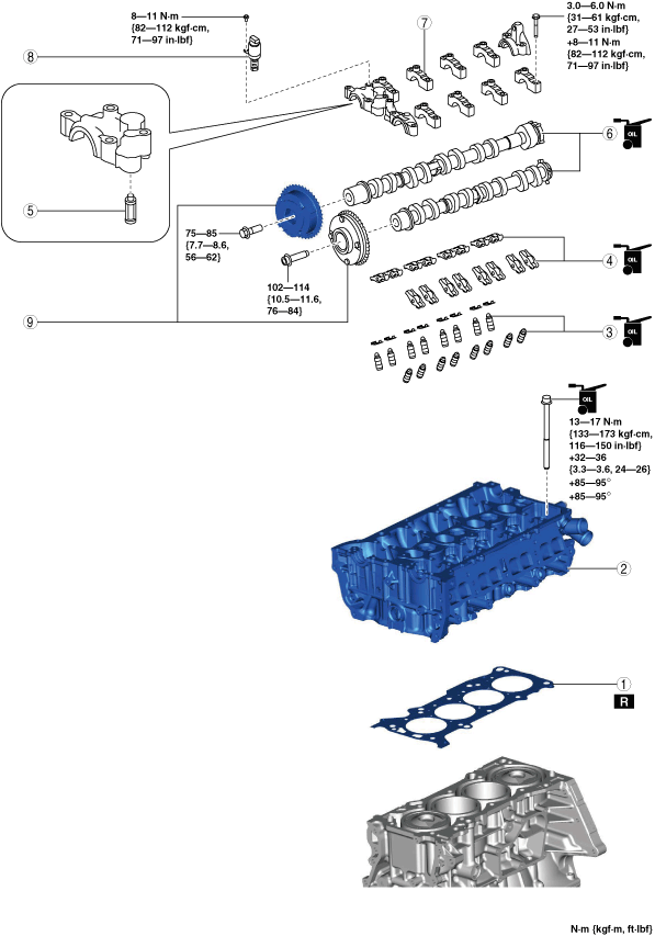
1. Assemble in the order indicated in the table.
|
1
|
Cylinder head gasket
|
|
2
|
Cylinder head
|
|
3
|
HLA
|
|
4
|
Rocker arm
|
|
5
|
OCV oil filter
|
|
6
|
Camshaft
|
|
7
|
Camshaft cap
|
|
8
|
OCV
|
|
9
|
Electric variable valve timing actuator, hydraulic variable valve timing actuator
|
Cylinder Head Assembly Note
-
Caution
-
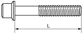
• If the following condition is met, replace the cylinder head bolts.
-
― Length exceeds maximum specification
-
Standard cylinder head bolt length L
-
145.2—145.8 mm {5.717—5.740 in}
-
Maximum cylinder head bolt length L
-
146.5 mm {5.767 in}
1. When a cylinder head bolt is reused, apply engine oil to any part of the following:
-
• Bolt seating surface
• Cylinder head seating surface
-
Caution
-
• Completely remove oil, dirt, and sealant adhering to the cylinder head gasket contacting surfaces. Otherwise, a sealing malfunction may occur.
2. Completely remove any oil, dirt, and sealant adhering to the cylinder block.
-
Caution
-
• Be aware of the following points, otherwise a sealing malfunction may occur due to hardening of the sealant.
-
― Set cylinder head on cylinder block within 10 min after silicone sealant is applied
― After setting cylinder head, tighten cylinder head bolts immediately
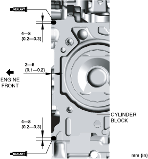
3. Apply silicone sealant (TB1217D or equivalent) to the areas shown in the figure.
-
Silicone sealant application diameter
-
5—10 mm {0.2—0.3 in}
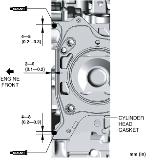
4. Install a new cylinder head gasket to the cylinder block.
5. Apply silicone sealant (TB1217D or equivalent) to the areas shown in the figure.
-
Silicone sealant application diameter
-
5—10 mm {0.2—0.3 in}
6. Set the cylinder head on the cylinder block.
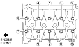
7. Tighten the cylinder head bolts in the order shown in the following four steps.
-
Tightening procedure
-
Step 1: 13—17 N·m {133—173 kgf·cm, 116—150 in·lbf}
Step 2: 32—36 N·m {3.3—3.6 kgf·m, 24—26 ft·lbf}
Step 3: 85—95°
Step 4: 85—95°
HLA Assembly Note
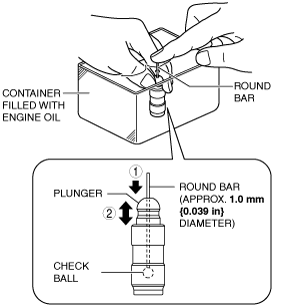
1. Perform HLA air bleeding using the following procedure:
- (1) Put the HLA in a container filled with engine oil.
-
-
Caution
-
• Do not insert the round bar firmly because the check ball spring force is extremely weak.
- (2) While lightly pressing the check ball using a round bar (approx. 1.0 mm {0.039 in} diameter), bleed air by moving the plunger up and down.
-
- (3) Press the end of the plunger in the oil and verify that there is no rebounding feel.
-
-
• If rebounding feel cannot be eliminated, replace the HLA.
2. Install the HLAs to their original positions as before removal. (intake side)
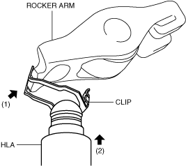
3. Apply engine oil to the HLAs surface where it contacts the rocker arms. (exhaust side)
4. Assemble the HLAs using the following procedure: (exhaust side)
- (1) Press the clip onto the rocker arm.
-
- (2) Insert the HLA from the underside of the clip.
-
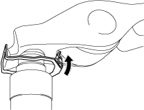
- (3) Press the clip in the direction of the arrow and install it to the rocker arm.
-
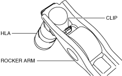
- (4) Verify that the tab of the clip is securely engaged to the rocker arm.
-
Rocker Arm Assembly Note
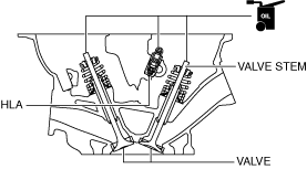
1. Apply engine oil to the HLAs and the end of the valve stems.
2. Install the rocker arms to their original positions as before removal. (intake side)
3. Install the rocker arms, clips and HLAs as a single unit to the same positions as before removal. (exhaust side)
Camshaft Assembly Note
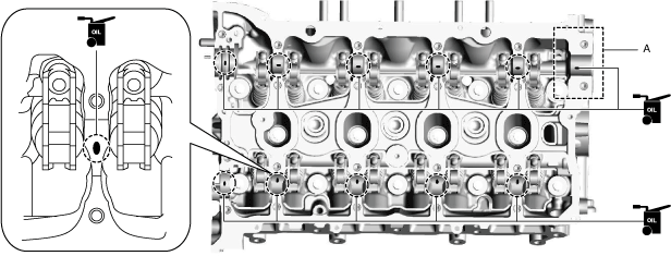
1. Apply SAE 90 gear oil or equivalent, or engine oil to the positions shown in the figure.
-
Caution
-
• Apply 0.05 ml {0.05 cc, 0.003 in3} or less of oil to area A in the figure.
2. Apply SAE 90 gear oil or equivalent, or engine oil to the following locations of each camshaft.
-
• Thrust surface of front journal (both surfaces front and back)
-
Note
-
• If oil is applied to the front camshaft cap, oil should not be applied to the thrust surface of the front journal.
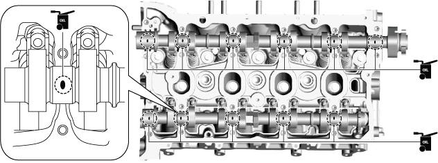
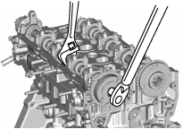
3. As shown in the figure, align the cam position of cylinder No.1 around top dead center (TDC) and place the camshafts on the cylinder head.
4. Apply SAE 90 gear oil or equivalent, or engine oil to the central area of each journal on the camshaft.
5. Apply SAE 90 gear oil or equivalent, or engine oil to the thrust surface of the front camshaft cap.
-
• If oil is applied to the front journal thrust surface of each camshaft, oil should not be applied to the front camshaft cap.
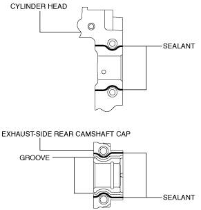
6. Apply sealant (Loctite #962T or equivalent) to the rear camshaft cap installation area on the exhaust side or the rear camshaft caps on the exhaust side of the cylinder head.
-
Note
-
• To prevent engine oil leakage, apply sealant to the rear camshaft cap installation area on the exhaust side or the rear camshaft caps on the exhaust side of the cylinder head, and seal the journal.
-
Caution
-
• Do not spill sealant on the journal.
-
Sealant bead width
-
1—3 mm {0.04—0.11 in}
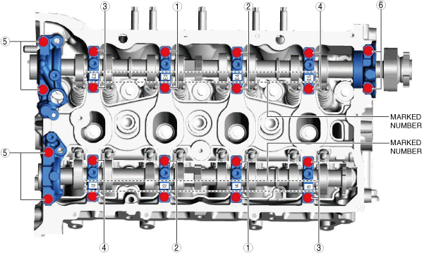
7. Install the camshaft caps in the marked number order, and temporarily tighten the camshaft cap installation bolts in two or three passes evenly.
8. Tighten the camshaft cap installation bolts in two steps in the order shown in the figure.
-
Tightening torque
-
Step 1: 3.0—6.0 N·m {31—61 kgf·cm, 27—53 in·lbf}
Step 2: 8—11 N·m {82—112 kgf·cm, 71—97 in·lbf}
Electric Variable Valve Timing Actuator, Hydraulic Variable Valve Timing Actuator Assembly Note
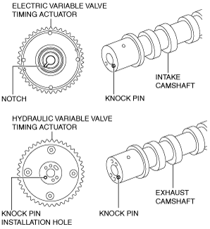
1. Align the knock pin on the end of the camshaft with the notch on the actuator (intake side) or knock pin installation hole (exhaust side), then install the actuator to the camshaft.
2. Hold the camshaft using a wrench on the cast hexagon, and tighten the actuator installation bolt.
-
Tightening torque
-
Electric variable valve timing actuator (intake side): 102—114 N·m {10.5—11.6 kgf·m, 76—84 ft·lbf}
Hydraulic variable valve timing actuator (exhaust side): 75—85 N·m {7.7—8.6 kgf·m, 56—62 ft·lbf}