 |
am2zzn00003516
ON-BOARD DIAGNOSTIC [CLIMATE CONTROL UNIT]
id0702k7126600
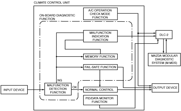
Outline
Block Diagram
am2zzn00003516
|
Function
Malfunction detection function
Memory function
Malfunction indication function
ac9wzn00001987
|
DTC table
|
DTC No. |
Warning/indicator light |
System malfunction location |
Fail-safe function |
Drive cycle |
Self test type*1 |
Memory function |
|---|---|---|---|---|---|---|
|
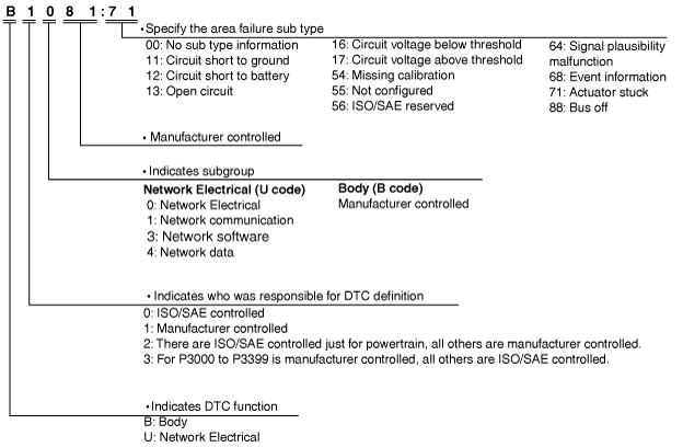
B1081:71
|
—
|
Driver-side front air mix actuator motor lock (L.H.D.)
Passenger-side front air mix actuator motor lock (R.H.D.)
|
X
|
—
|
C
|
X
|
|
B1082:71
|
—
|
Passenger-side front air mix actuator motor lock (L.H.D.)
Driver-side front air mix actuator motor lock (R.H.D.)
|
X
|
—
|
C
|
X
|
|
B1086:71
|
—
|
Front airflow mode actuator motor lock
|
X
|
—
|
C
|
X
|
|
B10FB:71
|
—
|
Air intake actuator motor lock
|
X
|
—
|
C
|
X
|
|
B1142:13
|
—
|
Rear climate control unit power supply circuit open (IG1)
|
—
|
—
|
C, D
|
X
|
|
B1143:13
|
—
|
Rear climate control unit power supply circuit open (IG2)
|
—
|
—
|
C, D
|
X
|
|
B11F0:12
|
—
|
Air intake actuator (potentiometer) circuit short to power supply
|
X
|
—
|
C, D
|
X
|
|
B11F0:13
|
—
|
Air intake actuator (potentiometer) circuit open
|
X
|
—
|
C, D
|
X
|
|
B11F5:86
|
—
|
Invalid data (temperature) received from humidity sensor
|
X
|
—
|
C, D
|
X
|
|
B1259:12
|
—
|
Rear airflow mode actuator (potentiometer) circuit short to power supply
|
X
|
—
|
C, D
|
X
|
|
B1259:13
|
—
|
Rear airflow mode actuator (potentiometer) circuit open
|
X
|
—
|
C, D
|
X
|
|
B1354:71
|
—
|
Rear air mix actuator motor lock
|
X
|
—
|
C
|
X
|
|
B13AB:12
|
—
|
Rear air mix actuator (potentiometer) circuit short to power supply
|
X
|
—
|
C, D
|
X
|
|
B13AB:13
|
—
|
Rear air mix actuator (potentiometer) circuit open
|
X
|
—
|
C, D
|
X
|
|
B1A61:11
|
—
|
Cabin temperature sensor circuit short to ground
|
X
|
—
|
C, D
|
X
|
|
B1A61:13
|
—
|
Cabin temperature sensor circuit open
|
X
|
—
|
C, D
|
X
|
|
B1A63:12
|
—
|
Solar radiation sensor (RH) circuit shot to power supply
|
X
|
—
|
C, D
|
X
|
|
B1A63:13
|
—
|
Solar radiation sensor (RH) circuit open
|
X
|
—
|
D
|
X*2/—*3
|
|
B1A64:12
|
—
|
Solar radiation sensor (LH) circuit shot to power supply
|
X
|
—
|
C, D
|
X
|
|
B1A64:13
|
—
|
Solar radiation sensor (LH) circuit open
|
X
|
—
|
D
|
X*2/—*3
|
|
B1A69:86
|
—
|
Invalid data (humidity) received from humidity sensor
|
X
|
—
|
C, D
|
X
|
|
B1B71:11
|
—
|
Evaporator temperature sensor circuit short to ground
|
X
|
—
|
C, D
|
X
|
|
B1B71:13
|
—
|
Evaporator temperature sensor circuit open
|
X
|
—
|
C, D
|
X
|
|
B1B7D:71
|
—
|
Rear airflow mode actuator motor lock
|
X
|
—
|
C
|
X
|
|
B1C1A:12
|
—
|
Driver-side front air mix actuator (potentiometer) circuit short to power supply (L.H.D.)
Passenger-side front air mix actuator (potentiometer) circuit short to power supply (R.H.D.)
|
X
|
—
|
C, D
|
X
|
|
B1C1A:13
|
—
|
Driver-side front air mix actuator (potentiometer) circuit open (L.H.D.)
Passenger-side front air mix actuator (potentiometer) circuit open (R.H.D.)
|
X
|
—
|
C, D
|
X
|
|
B1C1B:12
|
—
|
Passenger-side front air mix actuator (potentiometer) circuit short to power supply (L.H.D.)
Driver-side front air mix actuator (potentiometer) circuit short to power supply (R.H.D.)
|
X
|
—
|
C, D
|
X
|
|
B1C1B:13
|
—
|
Passenger-side front air mix actuator (potentiometer) circuit open (L.H.D.)
Driver-side front air mix actuator (potentiometer) circuit open (R.H.D.)
|
X
|
—
|
C, D
|
X
|
|
B1C1C:12
|
—
|
Front airflow mode actuator (potentiometer) circuit short to power supply
|
X
|
—
|
C, D
|
X
|
|
B1C1C:13
|
—
|
Front airflow mode actuator (potentiometer) circuit open
|
X
|
—
|
C, D
|
X
|
|
U0010:88
|
—
|
Unit communication error (MS-CAN)
|
—
|
—
|
C
|
X
|
|
U0155:00
|
—
|
Communication error with instrument cluster
|
X
|
—
|
C, D
|
X
|
|
U0164:00
|
—
|
Communication error with front climate control unit
|
X
|
—
|
C, D
|
X
|
|
U0165:00
|
—
|
Communication error with rear climate control unit
|
X
|
—
|
C, D
|
X
|
|
U0423:68
|
—
|
Invalid data received from Instrument cluster
|
X
|
—
|
C, D
|
X
|
|
U0424:68
|
—
|
Rear climate control unit had invalid data received from front climate control unit
|
X
|
—
|
C, D
|
X
|
|
U0466:68
|
—
|
Front climate control unit had invalid data received from rear climate control unit
|
X
|
—
|
C, D
|
X
|
|
U200D:11
|
—
|
Front climate control unit circuit voltage (+5V) circuit short to ground
|
—
|
—
|
C, D
|
X
|
|
U200E:12
|
—
|
Rear climate control unit circuit voltage (+5V) circuit short to ground
|
—
|
—
|
C, D
|
X
|
|
U2101:54
|
—
|
Rear climate control unit configuration error (data not received)
|
—
|
—
|
C, D
|
X
|
|
U2101:55
|
—
|
Rear climate control unit configuration error (not configured)
|
—
|
—
|
C, D
|
—
|
|
U2101:56
|
—
|
Rear climate control unit configuration error (ineffective/non-interchangeable data read)
|
X
|
—
|
C, D
|
X
|
|
U2101:64
|
—
|
Rear climate control unit configuration error (error value read)
|
—
|
—
|
C, D
|
X
|
|
U210A:86
|
—
|
Invalid data (windshield temperature) received from humidity sensor
|
X
|
—
|
C, D
|
X
|
|
U2300:54
|
—
|
Front climate control unit configuration error (data not received)
|
—
|
—
|
C, D
|
X
|
|
U2300:55
|
—
|
Front climate control unit configuration error (not configured)
|
—
|
—
|
C, D
|
—
|
|
U2300:56
|
—
|
Front climate control unit configuration error (ineffective/non-interchangeable data read)
|
X
|
—
|
C, D
|
X
|
|
U2300:64
|
—
|
Front climate control unit configuration error (error value read)
|
—
|
—
|
C, D
|
X
|
|
U3003:16
|
—
|
Front climate control unit power supply circuit voltage below threshold (10.00 V or less)
|
—
|
—
|
C, D
|
X
|
|
U3003:17
|
—
|
Front climate control unit power supply circuit voltage above threshold (17.30 V or more)
|
—
|
—
|
C, D
|
X
|
|
U3006:16
|
—
|
Rear climate control unit power supply circuit voltage below threshold (10.00 V or less)
|
—
|
—
|
C, D
|
X
|
|
U3006:17
|
—
|
Rear climate control unit power supply circuit voltage above threshold (17.30 V or more)
|
—
|
—
|
C, D
|
X
|
|
U300E:13
|
—
|
Front climate control unit power supply circuit open (IG1)
|
—
|
—
|
C, D
|
X
|
|
U300F:13
|
—
|
Front climate control unit power supply circuit open (IG2)
|
—
|
—
|
C, D
|
X
|
ac5wzn00001320
|
ac5wzn00001326
|
PID/data monitor
PID/data monitor table
|
PID |
Unit/Condition |
Data contents |
Climate control unit terminal |
|---|---|---|---|
|
A/C_SW
|
Off/On
|
• Off: A/C switch is off.
• On: A/C switch is on.
|
—
|
|
AUTO_SW
|
Off/On
|
• Off: AUTO switch is off. (front climate control unit)
• On: AUTO switch is on. (front climate control unit)
|
—
|
|
B_MT_RLY_CS
|
Off/On
|
• Off: Blower relay is off.
• On: Blower relay is on.
|
—
|
|
DEF_SW
|
Off/On
|
• Off: DEFROSTER switch is off.
• On: DEFROSTER switch is on.
|
—
|
|
DUAL_SW
|
Off/On
|
• Off: DUAL switch is off.
• On: DUAL switch is on.
|
—
|
|
EATC_OUT_V
|
V
|
Front climate control unit output voltage is displayed.
|
1R
|
|
ENG_C_TMP
|
°C, °F
|
Engine coolant temperature is displayed.
|
—
|
|
EVA_TMP_SEN
|
°C, °F
|
Evaporator temperature is displayed.
|
1P
|
|
F_REC_CS
|
Off/On
|
• Off: Forced recirculate control is off.
• On: Forced recirculate control is on.
|
—
|
|
F_WIND_TEMP
|
°C, °F
|
Front windshield temperature is displayed.
|
—
|
|
FAN_DWN_SW
|
Off/On
|
• Off: Airflow volume control switch (DOWN) is off. (front climate control unit)
• On: Airflow volume control switch (DOWN) is on. (front climate control unit)
|
—
|
|
FAN_UP_SW
|
Off/On
|
• Off: Airflow volume control switch (UP) is off. (front climate control unit)
• On: Airflow volume control switch (UP) is on. (front climate control unit)
|
—
|
|
FUEL_TYPE
|
—
|
Fuel type is displayed.
|
—
|
|
HC_TMP_SEN
|
°C, °F
|
Heater core temperature is displayed.
|
—
|
|
HUMIDITY_SEN
|
%
|
Relative humidity is displayed.
|
—
|
|
INC_TMP_SEN
|
°C, °F
|
Cabin temperature is displayed.
|
—
|
|
M_DOWN_SW
|
Off/On
|
• Off: MODE switch (DOWN) is off. (front climate control unit)
• On: MODE switch (DOWN) is on. (front climate control unit)
|
—
|
|
M_UP_SW
|
Off/On
|
• Off: MODE switch (UP) is off. (front climate control unit)
• On: MODE switch (UP) is on. (front climate control unit)
|
—
|
|
OFF_SW
|
Off/On
|
• Off: OFF switch is off. (front climate control unit)
• On: OFF switch is on. (front climate control unit)
|
—
|
|
OUT_CAR_TMP
|
°C, °F
|
Ambient temperature is displayed.
|
—
|
|
R/DEF_CS
|
Off (enable)/
Off (suspend)/
Off (inhibit)/
On
|
• Off (enable): Rear window defogger is off (operation enabled).
• Off (suspend): Rear window defogger is off (operation interrupted / indicator is kept On).
• Off (inhibit): Rear window defogger is off (operation disabled / indicator is turned Off).
• On: Rear window defogger is on.
|
—
|
|
R/DEF_SW
|
Off/On
|
• Off: Rear window defogger switch is off.
• On: Rear window defogger switch is on.
|
—
|
|
R_AUTO_SW
|
Off/On
|
• Off: AUTO switch is off. (rear climate control unit)
• On: AUTO switch is on. (rear climate control unit)
|
—
|
|
R_EATC_OUT_V
|
V
|
Rear climate control unit output voltage is displayed.
|
W
|
|
R_FAN_DN_SW
|
Off/On
|
• Off: Airflow volume control switch (DOWN) is off. (rear climate control unit)
• On: Airflow volume control switch (DOWN) is on. (rear climate control unit)
|
—
|
|
R_FAN_UP_SW
|
Off/On
|
• Off: Airflow volume control switch (UP) is off. (rear climate control unit)
• On: Airflow volume control switch (UP) is on. (rear climate control unit)
|
—
|
|
R_MODE_SW
|
Off/On
|
• Off: MODE switch is off. (rear climate control unit)
• On: MODE switch is on. (rear climate control unit)
|
—
|
|
R_OFF_SW
|
Off/On
|
• Off: OFF switch is off. (rear climate control unit)
• On: OFF switch is on. (rear climate control unit)
|
—
|
|
R_TEMP_DN_SW
|
Off/On
|
• Off: Temperature control switch (DOWN) is off. (rear climate control unit)
• On: Temperature control switch (DOWN) is on. (rear climate control unit)
|
—
|
|
R_TEMP_UP_SW
|
Off/On
|
• Off: Temperature control switch (UP) is off. (rear climate control unit)
• On: Temperature control switch (UP) is on. (rear climate control unit)
|
—
|
|
R_VPWR
|
V
|
Rear climate control unit supply voltage is displayed.
|
V
|
|
REAR_SW
|
Off/On
|
• Off: REAR switch is off. (front climate control unit)
• On: REAR switch is on. (front climate control unit)
|
—
|
|
REC_SW
|
Off/On
|
• Off: RECIRCULATE switch is off.
• On: RECIRCULATE switch is on.
|
—
|
|
RLS_TEMP
|
°C, °F
|
Humidity sensor temperature is displayed.
|
—
|
|
RSH_L_CTRL_ST*1
|
Off/Lo/Mid/Hi
|
• Off: SEAT WARMER (LH) switch is off.
• Lo: SEAT WARMER (LH) switch is lo.
• Mid: SEAT WARMER (LH) switch is mid.
• Hi: SEAT WARMER (LH) switch is hi.
|
—
|
|
RSH_L_SW_ST*1
|
Off/On
|
• Off: SEAT WARMER (LH) is off.
• On: SEAT WARMER (LH) is on.
|
—
|
|
RSH_L_SW_ST*2
|
|
||
|
RSH_R_CTRL_ST*1
|
Off/Lo/Mid/Hi
|
• Off: SEAT WARMER (RH) switch is off.
• Lo: SEAT WARMER (RH) switch is lo.
• Mid: SEAT WARMER (RH) switch is mid.
• Hi: SEAT WARMER (RH) switch is hi.
|
—
|
|
RSH_R_SW_ST*1
|
Off/On
|
• Off: SEAT WARMER (RH) is off.
• On: SEAT WARMER (RH) is on.
|
—
|
|
RSH_R_SW_ST*2
|
|
||
|
SLR_R_SEN_L
|
W/m2
|
Solar radiation amount is displayed.
|
1L
|
|
SLR_R_SEN_R
|
1J
|
||
|
STOP_ST
|
Available/
Not Available/
Error
|
• Available: i-stop permit request signal is sent.
• Not Available: i-stop inhibit request is sent.
• Error: i-stop signal error is sent.
|
—
|
|
UNIT_TMP
|
deg_C/deg_F
|
Unit of temperature is displayed.
• deg_C: Centigrade is selected.
• deg_F: Fahrenheit is selected.
|
—
|
|
VPWR
|
V
|
Front climate control unit supply voltage is displayed.
|
1U
|
A/C Operation Check Mode
ac9wzn00001987
|
|
M-MDS display |
Target part |
Reference |
|---|---|---|
|
Air Mix Actuator
|
• Front air Mix Actuator
• Front air mix door
|
(See Front air mix actuator)
|
|
Air conditioning compressor
|
• A/C compressor
|
(See A/C compressor)
|
|
Air Intake Actuator
|
• Air intake actuator
• Air intake door
|
(See Air intake actuator)
|
|
Blower Motor Speed
|
• Front blower motor
|
(See Front blower motor)
|
|
Airflow Mode Actuator
|
• Front airflow mode actuator
• Front airflow mode door
|
|
|
Illumination Of All Indicator Lights
|
• Climate control unit
|
(See Indicator light)
|
Front air mix actuator
1. Connect the M-MDS to the DLC-2.
2. Switch the ignition ON (engine on).
3. After the vehicle is identified, select the following items from the initial screen of the M-MDS.
4. Select the “Air Mix Actuator” from the screen menu.
5. Verify the A/C operation check mode according to the directions on the screen.
6. Select “Stop” to stop the A/C operation check. (See A/C operation check stop.)
Operation
|
Step |
Front air mix actuator |
Front airflow mode actuator |
Front blower speed |
Magnet clutch |
Air intake actuator |
Rear air mix actuator |
Rear airflow mode actuator |
Rear blower speed |
|---|---|---|---|---|---|---|---|---|
|
1
|
0 %
|
VENT
|
5th
|
ON
|
FRESH
|
0 %
|
VENT
|
5th
|
|
2
|
100 %
|
100 %
|
Display
|
Step |
Front climate control unit |
Rear climate control unit |
||||||||||
|---|---|---|---|---|---|---|---|---|---|---|---|---|
|
Temperature (°C {°F}) |
Airflow mode |
Blower volume |
A/C |
Recirculate switch indicator light |
Power switch indicator light*1 |
Other indicator lights |
Temperature (°C {°F}) |
Airflow mode |
Blower volume |
AUTO |
SYNC |
|
|
1
|
20.0 {68}
|
 |
 |
Displayed
|
Not illuminated
|
Illuminated
|
Not illuminated
|
20.0 {68}
|
|
 |
Not displayed
|
Not displayed
|
|
2
|
21.0 {70}
|
21.0 {70}
|
||||||||||
A/C compressor
1. Connect the M-MDS to the DLC-2.
2. Switch the ignition ON (engine on).
3. After the vehicle is identified, select the following items from the initial screen of the M-MDS.
4. Select the “Air conditioning compressor” from the screen menu.
5. Verify the A/C operation check mode according to the directions on the screen.
6. Select “Stop” to stop the A/C operation check. (See A/C operation check stop.)
Operation
|
Step |
Front air mix actuator |
Front airflow mode actuator |
Front blower speed |
Magnet clutch |
Air intake actuator |
Rear air mix actuator |
Rear airflow mode actuator |
Rear blower speed |
|---|---|---|---|---|---|---|---|---|
|
1
|
0 %
|
VENT
|
5th
|
ON
|
FRESH
|
50 %
|
VENT
|
Off
|
|
2
|
OFF
|
Display
|
Step |
Front climate control unit |
Rear climate control unit |
||||||||||
|---|---|---|---|---|---|---|---|---|---|---|---|---|
|
Temperature (°C {°F}) |
Airflow mode |
Blower volume |
A/C |
Recirculate switch indicator light |
Power switch indicator light*2 |
Other indicator lights |
Temperature (°C {°F}) |
Airflow mode |
Blower volume |
AUTO |
SYNC |
|
|
1
|
4 {39}*1
8 {46}*2
|
|
|
Displayed
|
Not illuminated
|
Illuminated
|
Not illuminated
|
Not displayed
|
||||
|
2
|
Not displayed
|
|||||||||||
Air intake actuator
1. Connect the M-MDS to the DLC-2.
2. Switch the ignition ON (engine on).
3. After the vehicle is identified, select the following items from the initial screen of the M-MDS.
4. Select the “Air Intake Actuator” from the screen menu.
5. Verify the A/C operation check mode according to the directions on the screen.
6. Select “Stop” to stop the A/C operation check. (See A/C operation check stop.)
Operation
|
Step |
Front air mix actuator |
Front airflow mode actuator |
Front blower speed |
Magnet clutch |
Air intake actuator |
Rear air mix actuator |
Rear airflow mode actuator |
Rear blower speed |
|---|---|---|---|---|---|---|---|---|
|
1
|
0 %
|
VENT
|
5th
|
ON
|
FRESH
|
50 %
|
VENT
|
Off
|
|
2
|
RECIRCULATE (25%)
|
|||||||
|
3
|
RECIRCULATE (50%)
|
|||||||
|
4
|
RECIRCULATE (75%)
|
|||||||
|
5
|
RECIRCULATE (100%)
|
|||||||
|
6
|
OFF
|
RECIRCULATE (75%)
|
||||||
|
7
|
RECIRCULATE (50%)
|
|||||||
|
8
|
RECIRCULATE (25%)
|
|||||||
|
9
|
FRESH
|
Display
|
Step |
Front climate control unit |
Rear climate control unit |
||||||||||
|---|---|---|---|---|---|---|---|---|---|---|---|---|
|
Temperature (°C {°F}) |
Airflow mode |
Blower volume |
A/C |
Recirculate switch indicator light |
Power switch indicator light*1 |
Other indicator lights |
Temperature (°C {°F}) |
Airflow mode |
Blower volume |
AUTO |
SYNC |
|
|
1
|
4 {39}
|
|
|
Displayed
|
Not illuminated
|
Illuminated
|
Not illuminated
|
Not displayed
|
||||
|
2
|
Illuminated
|
|||||||||||
|
3
|
||||||||||||
|
4
|
||||||||||||
|
5
|
||||||||||||
|
6
|
Not displayed
|
Not illuminated
|
||||||||||
|
7
|
Illuminated
|
|||||||||||
|
8
|
||||||||||||
|
9
|
||||||||||||
Front blower motor
1. Connect the M-MDS to the DLC-2.
2. Switch the ignition ON (engine on).
3. After the vehicle is identified, select the following items from the initial screen of the M-MDS.
4. Select the “Blower Motor Speed” from the screen menu.
5. Verify the A/C operation check mode according to the directions on the screen.
6. Select “Stop” to stop the A/C operation check. (See A/C operation check stop.)
Operation
|
Step |
Front air mix actuator |
Front airflow mode actuator |
Front blower speed |
Magnet clutch |
Air intake actuator |
Rear air mix actuator |
Rear airflow mode actuator |
Rear blower speed |
|---|---|---|---|---|---|---|---|---|
|
1
|
50 %
|
VENT
|
OFF
|
OFF
|
FRESH
|
50 %
|
VENT
|
OFF
|
|
2
|
1st
|
ON
|
1st
|
|||||
|
3
|
3rd
|
3rd
|
||||||
|
4
|
5th
|
5th
|
||||||
|
5
|
7th
|
5th
|
Display
|
Step |
Front climate control unit |
Rear climate control unit |
||||||||||
|---|---|---|---|---|---|---|---|---|---|---|---|---|
|
Temperature (°C {°F}) |
Airflow mode |
Blower volume |
A/C |
Recirculate switch indicator light |
Power switch indicator light*1 |
Other indicator lights |
Temperature (°C {°F}) |
Airflow mode |
Blower volume |
AUTO |
SYNC |
|
|
1
|
1 {34}
|
|
Not displayed
|
Not displayed
|
Not illuminated
|
Not illuminated
|
Not illuminated
|
1 {34}
|
|
Not displayed
|
Not displayed
|
Not displayed
|
|
2
|
 |
Displayed
|
Illuminated
|
 |
||||||||
|
3
|
 |
 |
||||||||||
|
4
|
|
|
||||||||||
|
5
|
 |
|
||||||||||
Front airflow mode actuator
1. Connect the M-MDS to the DLC-2.
2. Switch the ignition ON (engine on).
3. After the vehicle is identified, select the following items from the initial screen of the M-MDS.
4. Select the “Airflow Mode Actuator” from the screen menu.
5. Verify the A/C operation check mode according to the directions on the screen.
6. Select “Stop” to stop the A/C operation check. (See A/C operation check stop.)
Operation
|
Step |
Front air mix actuator |
Front airflow mode actuator |
Front blower speed |
Magnet clutch |
Air intake actuator |
Rear air mix actuator |
Rear airflow mode actuator |
Rear blower speed |
|---|---|---|---|---|---|---|---|---|
|
1
|
50 %
|
VENT
|
5th
|
ON
|
FRESH
|
50 %
|
VENT
|
5th
|
|
2
|
BI-LEVEL
|
BI-LEVEL
|
||||||
|
3
|
HEAT
|
HEAT
|
||||||
|
4
|
DEF/HEAT
|
HEAT
|
||||||
|
5
|
DEFROSTER
|
HEAT
|
Display
|
Step |
Front climate control unit |
Rear climate control unit |
||||||||||
|---|---|---|---|---|---|---|---|---|---|---|---|---|
|
Temperature (°C {°F}) |
Airflow mode |
Blower volume |
A/C |
Recirculate switch indicator light |
Power switch indicator light*1 |
Other indicator lights |
Temperature (°C {°F}) |
Airflow mode |
Blower volume |
AUTO |
SYNC |
|
|
1
|
3 {37}
|
|
|
Displayed
|
Not illuminated
|
Illuminated
|
Not illuminated
|
3 {37}
|
|
|
Not displayed
|
Not displayed
|
|
2
|
 |
|
||||||||||
|
3
|
 |
|
||||||||||
|
4
|
 |
|
||||||||||
|
5
|
 |
|
||||||||||
Indicator light
1. Connect the M-MDS to the DLC-2.
2. Switch the ignition ON (engine on).
3. After the vehicle is identified, select the following items from the initial screen of the M-MDS.
4. Select the “Illumination Of All Indicator Lights” from the screen menu.
5. Verify the A/C operation check mode according to the directions on the screen.
6. Select “Stop” to stop the A/C operation check. (See A/C operation check stop.)
Operation
|
Step |
Front air mix actuator |
Front airflow mode actuator |
Front blower speed |
Magnet clutch |
Air intake actuator |
Rear air mix actuator |
Rear airflow mode actuator |
Rear blower speed |
|---|---|---|---|---|---|---|---|---|
|
—
|
50 %
|
VENT
|
OFF
|
OFF
|
FRESH
|
50 %
|
VENT
|
OFF
|
Display
|
Step |
Front climate control unit |
Rear climate control unit |
||||||||||
|---|---|---|---|---|---|---|---|---|---|---|---|---|
|
Temperature (°C {°F}) |
Airflow mode |
Blower volume |
A/C |
Recirculate switch indicator light |
Power switch indicator light*1 |
Other indicator lights |
Temperature (°C {°F}) |
Airflow mode |
Blower volume |
AUTO |
SYNC |
|
|
—
|
All indicator displayed
|
Illuminated
|
Illuminated
|
Illuminated
|
All indicator displayed
|
|||||||
A/C operation check stop
1. If “Stop” is selected while the A/C operation check is operating, the A/C stops at the conditions shown in the table.
Operation
|
Step |
Front air mix actuator |
Front airflow mode actuator |
Front blower speed |
Magnet clutch |
Air intake actuator |
Rear air mix actuator |
Rear airflow mode actuator |
Rear blower speed |
|---|---|---|---|---|---|---|---|---|
|
—
|
50 %
|
VENT
|
OFF
|
OFF
|
FRESH
|
50 %
|
VENT
|
OFF
|
Display
|
Step |
Front climate control unit |
Rear climate control unit |
||||||||||
|---|---|---|---|---|---|---|---|---|---|---|---|---|
|
Temperature (°C {°F}) |
Airflow mode |
Blower volume |
A/C |
Recirculate switch indicator light |
Power switch indicator light*1 |
Other indicator lights |
Temperature (°C {°F}) |
Airflow mode |
Blower volume |
AUTO |
SYNC |
|
|
—
|
0 {32}
|
|
Not displayed
|
Not displayed
|
Not illuminated
|
Not illuminated
|
Not illuminated
|
Not displayed
|
||||