• The seat warmer system consists of the following parts:
Front
ac9wzn00001833
|

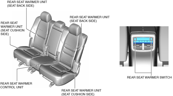
Rear
ac9wzn00001834
|
SEAT WARMER SYSTEM
id091300101200
Outline
Functions
Structure/Construction
Construction
Front
ac9wzn00001833
|
Rear
ac9wzn00001834
|
System wiring diagram
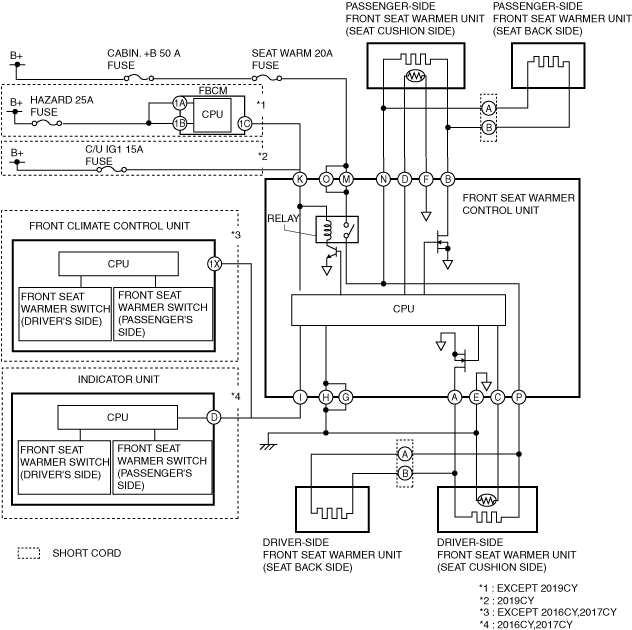
Front
ac9wzn00001835
|
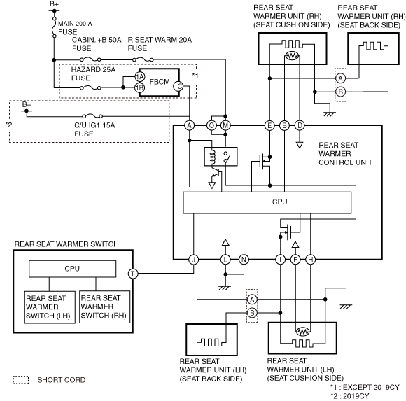
Rear
ac9wzn00001836
|
Operation
Front
1. When the seat warmer switch (driver) is operated (1), the indicator unit or the front climate control unit sends (2) a temperature level signal according to the seat warmer switch operation to the seat warmer control unit.
2. When the seat warmer control unit receives a temperature level signal from the indicator unit, it turns the transistor on (3) and the relay on (4).
3. When the relay turns on, power is supplied (5) to the driver's seat warmer unit and the seat warmer unit warms.
ac9uun00002566
|
Rear
1. When the CPU of the rear seat warmer switch detects the rear seat warmer switch (LH) operation, it sends (1) a switch operation signal (temperature level “3”) to the CPU of the rear seat warmer control unit.
2. When the CPU of the rear seat warmer control unit receives the switch operation signal (temperature level “3”) from the rear seat warmer switch, it sends current to the transistor to turn it on (2).
3. Current flows (3) to the FET by turning the transistor on.
4. The current flows (4) to the relay coil to turn the relay switch on (5).
5. When the relay switch is turned on, the ground circuit is established and the current flows (6) to the rear seat warmer unit in the rear seat cushion (LH) and rear seat back (LH).
6. The heating wire warms up (7) by the current sent to the rear seat warmer unit in the rear seat cushion (LH) and rear seat back (LH).
ac9wzn00001837
|
Fail-safe