FRONT COMBINATION LIGHT
id091800010200
Purpose
Without adaptive LED headlights
-
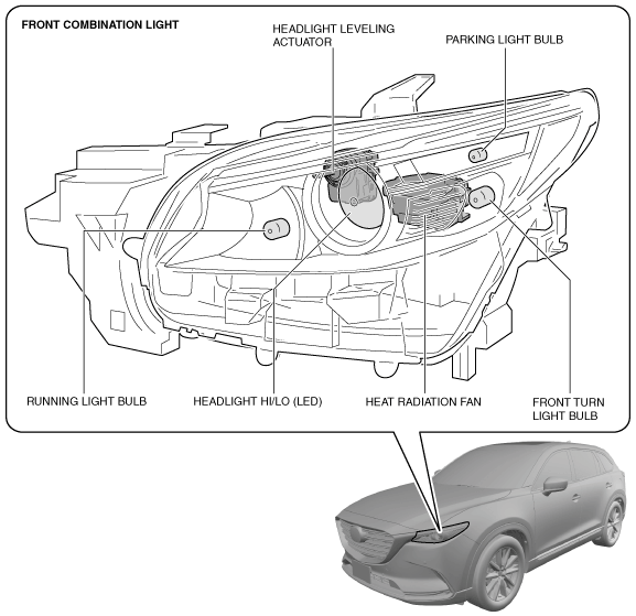
• The front combination light groups and houses together the parts related to the front exterior lights such as the headlight, parking light, running light, front turn light, headlight leveling actuator, wiring harnesses, and connectors.
• Energy consumption reduction and maintenance-free design been achieved with the adoption of LEDs on the headlight HI/LO.
• Visibility of road signs positioned higher up has been improved by blurring the cut lines of the headlights between light and dark to the extent possible.
• Visibility of pedestrians and roadside zones has been improved by expanding the light distribution of the headlights.
With adaptive LED headlights
-
• The front combination light groups and houses together the parts related to the front exterior lights such as the headlight, parking light/running light, front turn light, headlight leveling actuator, swivel actuator, wiring harnesses, and connectors.
• Energy consumption reduction and maintenance-free design been achieved with the adoption of LEDs on the headlight LO and HI, parking light/running light, and front turn light.
• Visibility of road signs positioned higher up has been improved by blurring the cut lines of the headlights between light and dark to the extent possible.
• Visibility of pedestrians and roadside zones has been improved by expanding the light distribution of the headlights.
Function
• Each light illuminates or flashes when the light switch, turn switch, or hazard warning switch is operated.
Structure/Construction
Without adaptive LED headlights
-
• The front combination light groups the following parts:
-
― Parking light bulb
― Running light bulb
― Front turn light bulb
• The front combination light is integrated with the following parts:
-
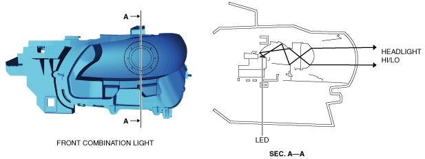
― Headlight HI/LO (LED)
― Headlight leveling actuator
• A projector type headlight has been adopted for the headlight HI/LO.
• Heat generated by the illumination of the LEDs is absorbed and dispersed by the heat radiation fan installed to the back of the headlight HI/LO reflector.
-
Note
-
• Fogging or condensation on the inside of the front combination lights may occur, however, it is a natural phenomenon occurring as a result of a temperature difference between the interior and exterior of the front combination lights and has no effect on the light performance.
• Fogging or condensation occurring as a natural phenomenon will dissipate when the temperature inside the front combination lights rises after the headlights are illuminated and a period of time has elapsed.
-
• The optimized shape of the headlight HI/LO reflector emits light over a wide area.
With adaptive LED headlights
-
• The front combination light is integrated with the following parts:
-
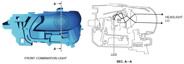
― Headlight LO (LED)
― Headlight HI (LED)
― Parking light/Running light/Front turn light (LED)
― Side-illuminating LED
― Headlight leveling actuator
• A projector type headlight has been adopted for the headlight LO.
• Heat generated by the illumination of the LEDs is absorbed and dispersed by the heat radiation plates installed near the light-emitting area of the headlight LO, headlight HI, parking lights/running lights, and front turn lights.
-
Note
-
• Fogging or condensation on the inside of the front combination lights may occur, however, it is a natural phenomenon occurring as a result of a temperature difference between the interior and exterior of the front combination lights and has no effect on the light performance.
• Fogging or condensation occurring as a natural phenomenon will dissipate when the temperature inside the front combination lights rises after the headlights are illuminated and a period of time has elapsed.
-
• The optimized shape of the headlight LO reflector emits light over a wide area.
Operation
Headlight LO
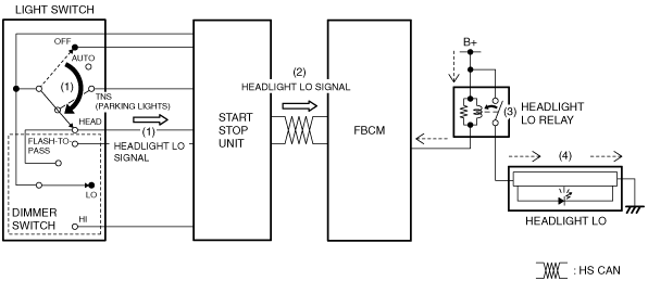
1. When the light switch is moved to the HEAD position and the dimmer switch is moved to the LO position, the start stop unit detects (1) a headlight LO signal.
2. The start stop unit sends (2) the headlight LO signal to the front body control module (FBCM) via CAN communication.
3. When the front body control module (FBCM) receives the headlight LO signal with the ignition switched ON (engine off or on), it turns (3) the headlight LO relay on.
4. When the headlight LO relay turns on, the headlight LO is illuminated (4).
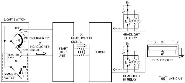
Headlight HI
1. When the light switch is moved to the HEAD position and the dimmer switch is moved to the HI position, the start stop unit detects (1) a headlight HI signal.
2. The start stop unit sends (2) the headlight HI signal to the front body control module (FBCM) via CAN communication.
3. When the front body control module (FBCM) receives the headlight HI signal with the ignition switched ON (engine off or on), it turns (3) the headlight LO and HI relays on.
4. When the headlight LO and HI relays turn on, the headlight HI is illuminated (4).
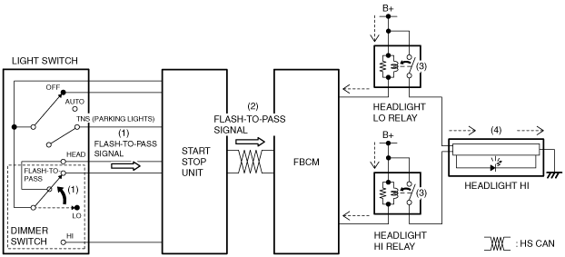
Flash-to-pass
1. When the dimmer switch is moved to the FLASH-TO-PASS position, the start stop unit detects (1) a FLASH-TO-PASS signal.
2. The start stop unit sends (2) the FLASH-TO-PASS signal to the front body control module (FBCM) via CAN communication.
3. When the front body control module (FBCM) receives the FLASH-TO-PASS signal with the ignition switched ON (engine off or on), it turns (3) the headlight LO and HI relays on.
4. When the headlight LO and HI relays turn on, the headlight HI is illuminated (4).
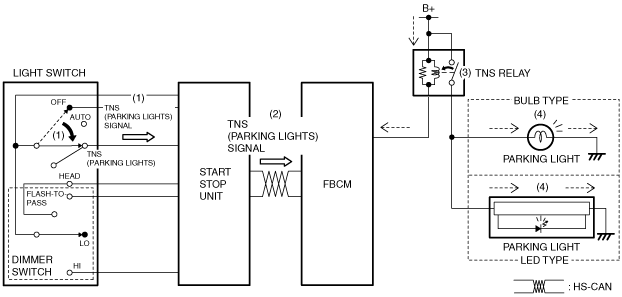
Parking light
1. When the light switch is moved to the TNS (parking lights) position, the start stop unit detects (1) a TNS (parking lights) signal.
2. The start stop unit sends (2) the TNS (parking lights) signal to the front body control module (FBCM) via CAN communication.
3. When the front body control module (FBCM) receives the TNS (parking lights) signal, it turns (3) the TNS relay on.
4. When the TNS relay turns on, the parking lights are illuminated (4).
Front turn light
-
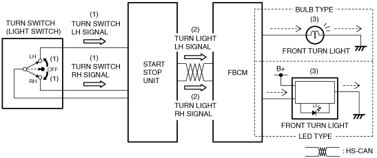
Turn light system
-
1. When the turn switch is moved to the LH or RH position with the ignition switched ON (engine off or on), the start stop unit detects (1) a turn switch LH or RH signal.
2. The start stop unit sends (2) the turn switch LH or RH signal to the front body control module (FBCM) via CAN communication as a turn light LH or RH signal.
3. When the front body control module (FBCM) receives the turn light LH or RH signal, it flashes (3) the front turn light (LH) or (RH).
-
Hazard warning system
-
1. When the hazard warning switch is turned on (1), the start stop unit detects (2) a hazard warning switch on signal.
2. The start stop unit sends (3) the hazard warning switch on signal to the front body control module (FBCM) via CAN communication as a turn light LH and RH signal.
3. When the front body control module (FBCM) receives the turn light LH and RH signal, it flashes (4) the front turn lights (LH) and (RH).
Side-illuminating LED (With adaptive LED headlights)
-
Headlight leveling actuator
-
Fail-safe
• Not applicable