 |
ac9wzn00001242
PARKING ASSIST SYSTEM
id092000014000
Outline
Function
Rear view monitor display function
Guide line display
Guide line display (With fixed assist lines display type)
Predicted vehicle track display (With predicted vehicle path assist lines display type)
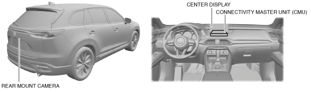
Structural View
ac9wzn00001242
|
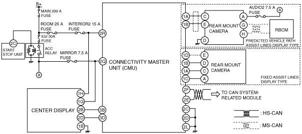
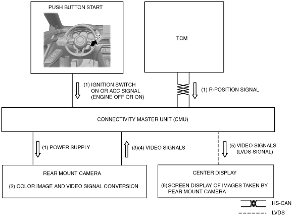
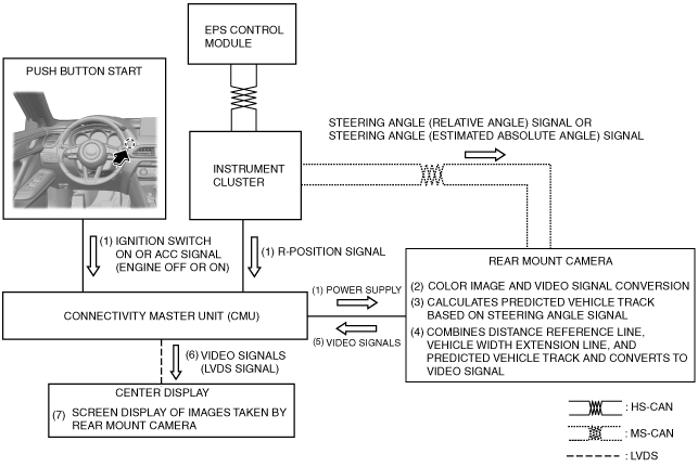
Block diagram
ac9wzn00001665
|
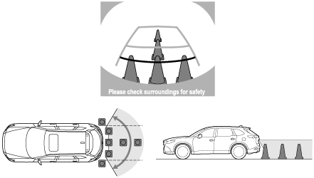
Image range
ac9uun00001035
|
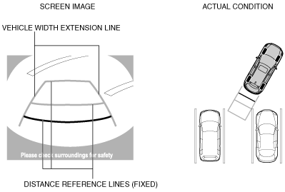
Rear view monitor screen
Guide line display (With fixed assist lines display type)
ac9wzn00001244
|
|
Display item |
Display line color |
Function |
|---|---|---|
|
Distance reference lines (fixed)
|
Red
|
• Shows distance reference line 0.5 m {20 in}from the rear of the rear bumper.
• Not in conjunction with steering operation.
|
|
Yellow
|
• Shows distance reference line 1.0 m {39 in} from the rear of the rear bumper.
• Not in conjunction with steering operation.
|
|
|
Yellow
|
• Shows distance reference line 2.3 m {91 in}from the rear of the rear bumper.
• Not in conjunction with steering operation.
|
|
|
Vehicle width extension line
|
Yellow
|
• Vehicle width extension line.
|
|
Bumper area
|
Black
|
• Displays the rear bumper area.
|
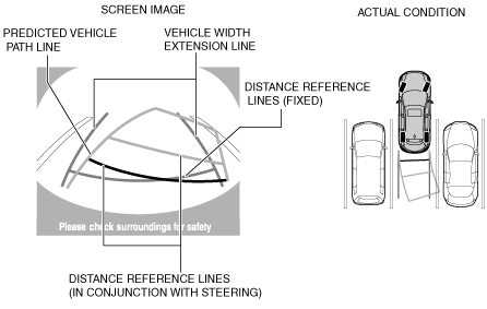
Predicted vehicle track display (With predicted vehicle path assist lines display type)
ac9wzn00001245
|
|
Display item |
Display line color |
Content |
|---|---|---|
|
Distance reference line (in conjunction with steering)
|
Red
|
• Shows distance reference line 0.5 m {20 in} from the rear of the rear bumper.
• Display changes in conjunction with the steering operation.
|
|
Yellow
|
• Shows distance reference line 1.0 m {39 in} from the rear of the rear bumper.
• Display changes in conjunction with the steering operation.
|
|
|
Yellow
|
• Shows distance reference line 2.3 m {106 in} from the rear of the rear bumper.
• Display changes in conjunction with the steering operation.
|
|
|
Distance reference lines (fixed)
|
Blue
|
• Shows distance reference line 0.5 m {20 in} from the rear of the rear bumper.
• Not in conjunction with steering operation.
|
|
Vehicle width extension line
|
Blue
|
• Vehicle width extension line.
|
|
Predicted vehicle path line
|
Yellow
|
• Calculated vehicle path based on steering angle signal.
• Predicted vehicle path which expresses the vehicle outermost circumference in conjunction with the steering operation.
|
Operation
Guide line display (With fixed assist lines display type)
ac9wzn00001246
|
Predicted vehicle track display (With predicted vehicle path assist lines display type)
ac9wzn00001247
|