ACTIVE DRIVING DISPLAY
id092200037300
Purpose
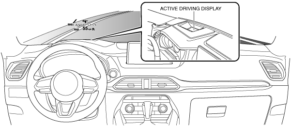
• The active driving display indicates the vehicle speed, warnings, and navigation information on the windshield, allowing verification of the information with only the slightest change in the line of vision.
Functions
• The active driving display indicates the following information.
-
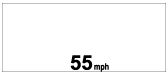
― Current vehicle speed
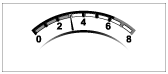
― Engine rotation speed
― Blind spot monitoring (BSM) system warning indication (With blind spot monitoring (BSM) system)
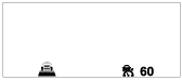
― Mazda radar cruise control (MRCC) system operation status or warning indication (With MRCC system)
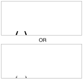
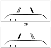
― Lane departure warning system (LDWS) operation status or warning indication (With LDWS)
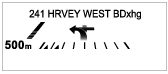
― Travel direction (turn by turn (TBT)) indication or navigation information (With car navigation system)
― Charging and high engine coolant temperature warning
• When the engine is started, the instrument cluster displays the following content on the active driving display based on the following CAN signals. For details on each display content, refer to each reference.
|
CAN signal sending module
|
Signal name
|
Display content
|
Display example
|
Reference
|
|
Instrument cluster
|
Vehicle speed signal
|
Current vehicle speed
|
 |
|
|
Engine speed signal
|
Engine rotation speed
|
 |
|
|
Instrument cluster
|
Warning display request signal
|
Warning screen
|
 |
|
|
Radar unit (MRCC system)
|
Operation condition display request signal
|
Distance between vehicles and set vehicle speed
|
 |
|
|
Warning display request signal
|
Warning screen
|
 |
|
Warning screen
|
 |
|
Radar unit (SBS)
|
Warning display request signal
|
Warning screen
|
|
|
|
Laser sensor (SCBS)
|
Warning display request signal
|
Warning screen
|
|
|
|
Forward sensing camera (FSC)
|
Operation display request signal
|
Vehicle lane display
|
 |
|
|
Warning display request signal
|
Warning screen
|
 |
|
Forward sensing camera (FSC)
|
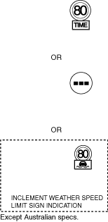
Speed limit signs
|
Warning screen
|
 |
|
|
Do not enter sign
|
Warning screen
|
 |
|
Stop sign
|
Warning screen
|
 |
|
Connectivity Master Unit
|
Turn-by-turn (TBT) display request signal/navigation information display request signal
|
Travel direction indication/navigation information
|
 |
|
|
Instrument cluster
|
Warning display request signal
|
Warning screen
|
 |
|
 |
|
Setting function
-
• The following items for the active driving display can be set on the [Settings] screen of the center display.
-
Note
-
• The indication position, brightness level, and display information of the active driving display is stored in the position memory control module during seat position programming. (With position memory system) For the seat position programming method, refer to the [POSITION MEMORY SYSTEM]. (See
POSITION MEMORY SYSTEM.)
|
Item
|
Setting contents
|
|
Height
|
The height of the displayed image can be adjusted.
|
|
Brightness adjustment
|
The brightness of the displayed image can be switched between automatic/manual.
|
|
Brightness level
|
The automatic dimness adjustment level can be switched.
(Brightness adjustment must be set to automatic.)
|
|
Illumination level
|
The brightness of the displayed image can be adjusted.
(Brightness adjustment must be set to manual.)
|
|
Rotate
|
The tilt of the displayed image can be adjusted.
|
|
Navigation system guidance
|
The turn-by-turn (TBT) display can be switched on/off.
|
|
Street name display
|
The street name display can be switched on/off.
|
|
Tachometer
|
The tachometer display can be switched on/off.
|
|
Display
|
Display/non-display of the active driving display can be switched.
|
|
Reset
|
The active driving display settings can be reset to the initial settings.
|
Demonstration function
-
Note
-
• The demonstration function force-displays the active driving display without the engine being started, such as on an indoor exhibition vehicle, so that customers can verify the display status.
-
• The demonstration function launches the active driving display with the ignition switched ON (engine off) to display the vehicle information in the display.
Demonstration function on/off setting procedure
-
1. After switching the ignition ON (engine off), switch the light switch within 5 s as follows.
-
• OFF→TNS (parking lights)→OFF→TNS (parking lights)→OFF→TNS (parking lights)→OFF
2. Switch the light switch (dimmer switch) within 5 s after Step 1 as follows.
-
• OFF→Headlight HI ON→OFF→Headlight HI ON→OFF→Headlight HI ON→OFF
3. Switch the light switch as follows to display the [Demonstration Mode ON] or [Demonstration Mode OFF] on the display screen of the active driving display.
-
• OFF→TNS (parking lights)→OFF→TNS (parking lights)→OFF→TNS (parking lights)→OFF→TNS (parking lights)→OFF→TNS (parking lights)→OFF→TNS (parking lights)→OFF
4. Switch the light switch (dimmer switch) to OFF→Headlight HI ON→OFF to turn on/off the demonstration function.
-
Note
-
• Select [Demonstration Mode ON] to turn on the demonstration function.
• Select [Demonstration Mode OFF] to turn off the demonstration function.
5. Switch the ignition OFF (LOCK).
-
Note
-
• If the ignition is switched OFF (LOCK) with [Demonstration Mode ON] displayed on the display screen of the active driving display (demonstration function on), the demonstration function will operate the next time the ignition is switched ON (engine off).
• If the following is performed with the demonstration function on, the demonstration function turns off.
-
― The battery power is interrupted or the ROOM fuse is removed.
― The vehicle is driven at 20 km/h or more.
Structure/Construction
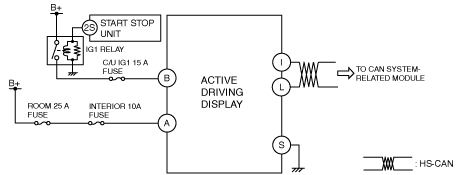
System wiring diagram
Construction
-
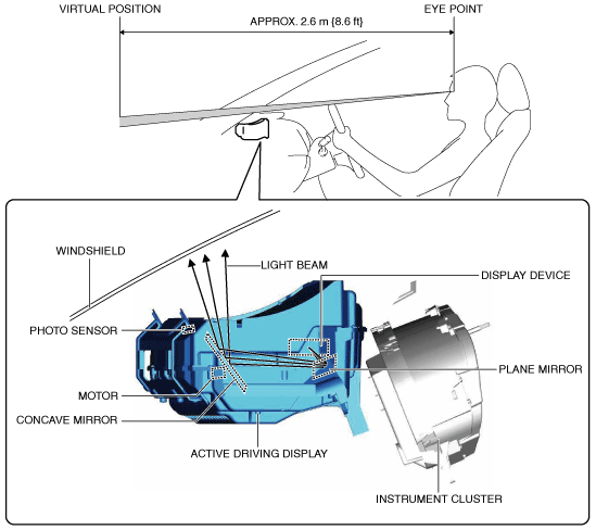
• The active driving display consists of a display device which produces the display content and emits the content over a light beam, a plane mirror which reflects the light beam emitted from the display device, a concave mirror which emits the light beam from the plane mirror to the windshield and enhances the display, a motor which changes the tilt of the concave mirror, and a photo sensor which detects the brightness of the driving condition.
• The time in which the driver's line of vision changes from the view at the front of the vehicle to the view of the information reflected on the windshield has been shortened by displaying the information within the forward visual range of the driver.
• The image reflected in the windshield is positioned virtually
approx. 2.6 m forward of the eye point. As a result, the eye point adjustment time in which the driver's line of vision changes from the view at the front of the vehicle to the view of the information reflected in the windshield has been reduced.
Operation
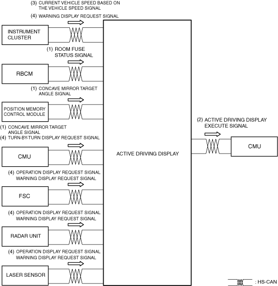
1. When the ignition is switched ON (engine on), the active driving display starts (1) the operation based on the following CAN signals.
-
― ROOM fuse status signal from rear body control module (RBCM)
― Concave mirror target angle signal from connectivity master unit (CMU)
-
Note
-
• When the position memory switch is operated, the active driving display adjusts the angle of the combiner based on the CAN signal (1) from the position memory control module.
2. The active driving display displays the opening screen
for approx. 2 s. In addition, it sends an active driving display execute signal (2) to the connectivity master unit (CMU).
-
Note
-
• The connectivity master unit (CMU) records the current position of the concave mirror based on the concave mirror current position signal from the active driving display. When the ignition is switched from OFF (LOCK) to ON (engine on), it sends the target angle signal based on the recorded concave mirror current position.
• The concave mirror current position recorded by the connectivity master unit (CMU) is not cleared even if the battery power is disconnected.
• If the connectivity master unit (CMU) has not recorded the concave mirror current position, it sends the target angle signal of the initial value.
3. After the opening screen is turned off, the active driving display displays the current vehicle speed based on the vehicle speed signal (3) from the PCM, and displays the warning or other screens based on request signals (4) from related modules.
Fail-safe
• When the active driving display detects a malfunction in the concave mirror drive motor, it turns off the windshield images.