ac9wzn00001493
|
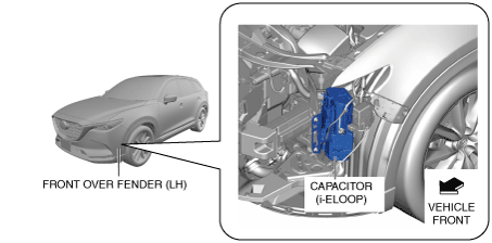
CAPACITOR (i-ELOOP) [i-ELOOP]
id131704502000
Purpose, Function
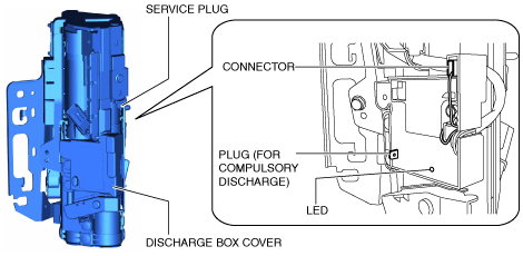
Construction
ac9wzn00001493
|
|
Part name |
Purpose |
|---|---|
|
Service plug
|
Interrupts short-circuit current to prevent a short to the 24.3 V related electricity stored in the capacitor (i-ELOOP) during servicing and the flow of large amounts of current.
|
|
Temperature sensor
|
Detects the capacitor (i-ELOOP) temperature for the purpose of assuring capacitor (i-ELOOP) performance because capacitor (i-ELOOP) performance deterioration is caused by a continuous capacitor (i-ELOOP) high temperature.
|
|
Capacitor (i-ELOOP) relay
|
Switches the electric circuit when the ignition is switched off, when in pre-charge mode for i-ELOOP operation, if the vehicle is in a collision, and when it is in fail-safe.
|
|
Plug (for compulsory discharge)
|
Equipped to the resistor on the capacitor (i-ELOOP) so that it can be disposed of after discharging the capacitor (i-ELOOP) for the purpose of assuring safety. The capacitor (i-ELOOP) can be transported safety by the compulsory discharge of the capacitor (i-ELOOP) using the resistor.
|
|
LED
|
Turns on the LED during compulsory capacitor (i-ELOOP) discharging.
|
ac9wzn00001494
|
am2zzn00003848
|
|
Terminal signal |
Input/output |
|---|---|
|
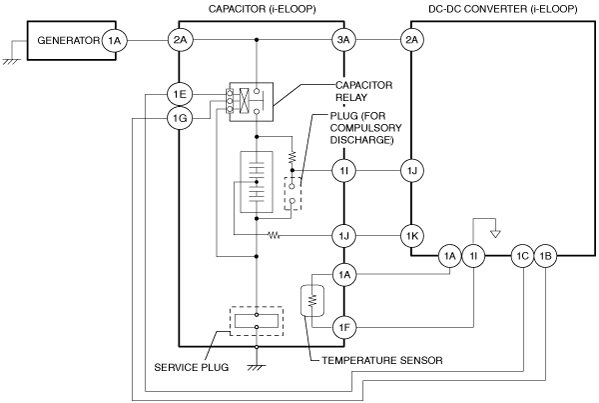
2A
|
Power input from generator.
|
|
3A
|
Electricity output to DC-DC converter (i-ELOOP).
|
|
1A
|
Temperature sensor signal output to DC-DC converter (i-ELOOP).
|
|
1E
|
Electricity output to DC-DC converter (i-ELOOP).
|
|
1F
|
GND (Temperature sensor)
|
|
1G
|
Electricity output to DC-DC converter (i-ELOOP).
|
|
1I
|
Electricity input/output to DC-DC converter (i-ELOOP).
|
|
1J
|
Electricity input/output to DC-DC converter (i-ELOOP).
|
Operation
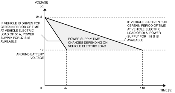
Capacitor (i-ELOOP) power
Ex.) Capacitor (i-ELOOP) voltage and power supply time relation
am2zzn00003849
|
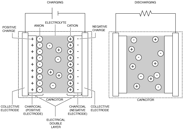
Capacitor (i-ELOOP) charge/discharge principles
am2zzn00003850
|
Capacitor (i-ELOOP) relay operation
|
When capacitor (i-ELOOP) relay is disconnected |
Outline |
|---|---|
|
Ignition is switched off
|
• To prevent a short to the 24.3 V related power or to reduce back-up current during servicing, the capacitor (i-ELOOP) relay is disconnected approx. 30 s after the ignition is switched OFF.
|
|
During collision
|
• The capacitor (i-ELOOP) relay is disconnected to assure safety in a vehicle collision.
|
|
In pre-charge mode for i-ELOOP operation
|
• The capacitor (i-ELOOP) relay is disconnected to assure excitation current to the generator when power from the battery is used (in pre-charge mode for i-ELOOP operation).
|
|
In fail-safe
|
• The capacitor (i-ELOOP) relay is disconnected while in fail-safe.
|
Fail-safe
DC-DC converter (i-ELOOP)
|
DTC |
Fail-safe |
|---|---|
|
P0A12:00
|
• Inhibits engine-stop by operating the i-stop function.
• Switches to bypass mode which shuts the capacitor (i-ELOOP) off.
|
|
P1794:00
|
• Inhibits engine-stop by operating the i-stop function.
• Inhibits the i-ELOOP control.
• Switches to bypass mode which shuts the capacitor (i-ELOOP) off.
|
|
P1794:01
|
|
|
P1794:13
|
|
|
P1794:14
|
|
|
P1794:1B
|
|
|
P1794:49
|
|
|
P1794:11
|
• Inhibits engine-stop by operating the i-stop function.
• Inhibits the i-ELOOP control.
• Inhibits the pre-charge control.
• Switches to bypass mode which shuts the capacitor (i-ELOOP) off.
|
PCM
|
DTC |
Fail-safe |
|---|---|
|
P2502:00
|
• Inhibits engine-stop by operating the i-stop function.
• Generator switch to default mode requested (14.5 V constant voltage power generation).
• Transition to i-ELOOP bypass mode.
|
|
P2504:00
|
• Inhibits engine-stop by operating the i-stop function.
• Generator switch to default mode requested. If the temperature of the generator exceeds the specified value, the generator itself stops power generation. But, if the internal circuit of the generator is malfunctioning, the generator may not accept the demand from the PCM.
|