 |
am2zzn00002658
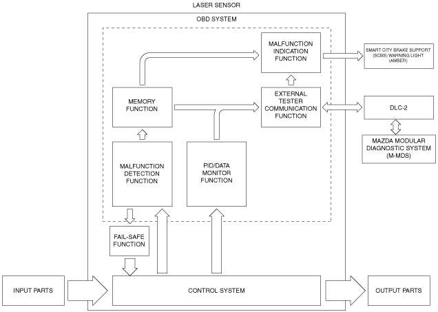
ON-BOARD DIAGNOSTIC SYSTEM [LASER SENSOR]
id1502b2705000
Outline
Block diagram
am2zzn00002658
|
Function
Malfunction detection function
Malfunction display function
Memory function
DTC table
|
DTC |
Master warning light |
Description |
Fail-safe |
Drive cycle |
Self test type*1 |
Memory function |
|---|---|---|---|---|---|---|
|
U0001:00
|
Illuminates
|
CAN line
|
×
|
—
|
C
|
×
|
|
U0100:00
|
||||||
|
U0121:00
|
||||||
|
U0131:00
|
||||||
|
U0155:00
|
||||||
|
U0401:00
|
Illuminates
|
Signal error from PCM
|
×
|
—
|
C
|
×
|
|
U0401:82
|
||||||
|
U0415:00
|
Illuminates
|
Signal error from DSC HU/CM
|
×
|
—
|
C
|
×
|
|
U0415:68
|
||||||
|
U0415:82
|
||||||
|
U0420:00
|
Illuminates
|
Signal error from EPS control module
|
×
|
—
|
C
|
×
|
|
U0420:82
|
||||||
|
U0423:00
|
Illuminates
|
Signal error from instrument cluster
|
×
|
—
|
C
|
×
|
|
U0423:82
|
||||||
|
U1A14:49
|
Illuminates
|
Laser sensor
|
×
|
—
|
C
|
×
|
|
U2300:54
|
Illuminates
|
Laser sensor configuration
|
×
|
—
|
C
|
×
|
|
U2300:55
|
||||||
|
U2300:56
|
||||||
|
U2300:64
|
||||||
|
U3000:00
|
Illuminates
|
Laser sensor (internal malfunction)
|
×
|
—
|
C
|
×
|
|
U3000:64
|
||||||
|
U3003:16
|
Not illuminate
|
Battery power supply
|
×
|
—
|
C
|
×
|
|
U3003:17
|
Status byte for DTC
am2zzn00002656
|
Fail-safe function
Fail-safe function table
|
DTC |
Smart City Brake Support (SCBS) control |
|---|---|
|
U0001:00
|
Control disabled
|
|
U0100:00
|
Control disabled
|
|
U0121:00
|
Control disabled
|
|
U0131:00
|
Control disabled
|
|
U0155:00
|
Control disabled
|
|
U0401:00
|
Control disabled
|
|
U0401:82
|
Control disabled
|
|
U0415:00
|
Control disabled
|
|
U0415:68
|
Control disabled
|
|
U0415:82
|
Control disabled
|
|
U0420:00
|
Control disabled
|
|
U0420:82
|
Control disabled
|
|
U0423:00
|
Control disabled
|
|
U0423:82
|
Control disabled
|
|
U1A14:49
|
Control disabled
|
|
U2300:54
|
Control disabled
|
|
U2300:55
|
Control disabled
|
|
U2300:56
|
Control disabled
|
|
U2300:64
|
Control disabled
|
|
U3000:00
|
Control disabled
|
|
U3000:64
|
Control disabled
|
|
U3003:16
|
Control disabled
|
|
U3003:17
|
Control disabled
|
PID/data monitor function
|
Monitor item |
Unit/Operation |
Test condition |
Specification (Reference) |
|---|---|---|---|
|
M-MDS display |
|||
|
DST_BMP_TGT
|
m, ft
|
This PID indicates distance from front bumper to target that laser sensor has detected.
|
|
|
VPWR_IG1
|
V
|
This PID indicates power supply voltage for laser sensor.
|
|
|
VSPD
|
KPH, MPH
|
This PID indicates vehicle speed.
|
|
External tester communication function
|
Diagnostic function name |
Signal received |
Signal sent |
|---|---|---|
|
Malfunction detection function
|
DTC verification signal
|
DTC(s)
|
|
PID/data monitor function
|
Command signal to read selected monitor item
|
Monitored data for requested monitor item
|
