 |
bawuua00000553
TRANSFER DISASSEMBLY (VEHICLES WITHOUT TRANSFER OIL COOLER)
id031600511100
Before Service Precautions
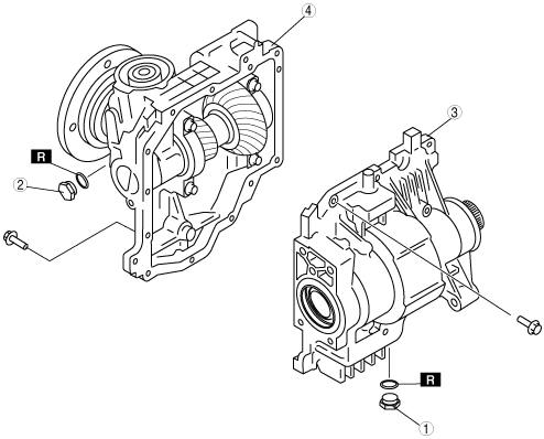
Transfer Component Disassembly
bawuua00000553
|
|
1
|
Drain plug
|
|
2
|
Oil level plug
|
|
3
|
Drive gear case component
|
|
4
|
Front carrier component
|
Transfer Component Disassembling Procedure
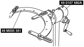
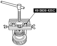
1. Assemble the SSTs.
bawuua00000168
|
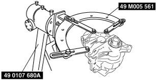
2. Install the transfer component to the SSTs.
bawuua00000169
|
3. Remove the drive gear case component.
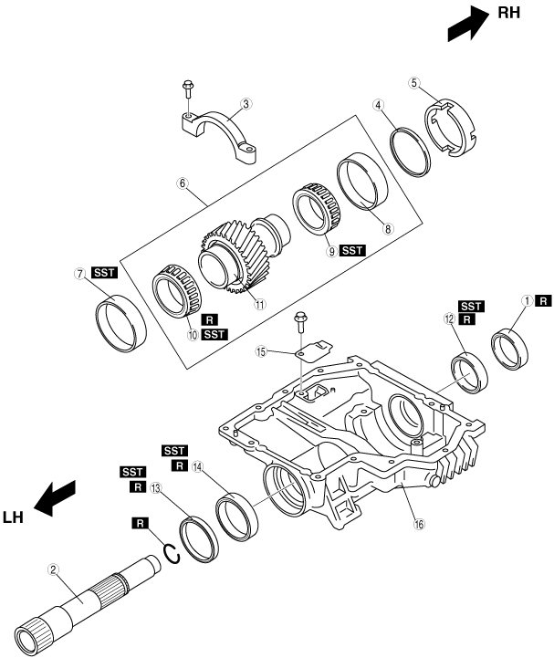
Drive Gear Case Component Disassembly
bawuua00000170
|
|
1
|
Oil seal (RH outer)
|
|
2
|
Drive gear shaft
|
|
3
|
Bearing cap
|
|
4
|
Adjustment shim
|
|
5
|
Spacer
|
|
6
|
Drive gear component
|
|
7
|
Bearing outer race (LH)
|
|
8
|
Bearing outer race (RH)
|
|
9
|
Bearing (RH)
|
|
10
|
Bearing (LH)
|
|
11
|
Drive gear
|
|
12
|
Oil seal (RH inner)
|
|
13
|
Oil seal (LH outer)
|
|
14
|
Oil seal (LH inner)
|
|
15
|
Baffle plate
|
|
16
|
Drive gear case
|
Drive Gear Case Component Disassembly Procedure
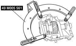
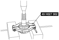
1. Install the drive gear case component to the SST.
bawuua00000171
|
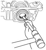
2. Tap the drive gear shaft using a suitable rod and hammer.
bawuua00000172
|
3. Take out the drive gear shaft from the drive gear case.
bawuua00000173
|
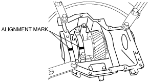
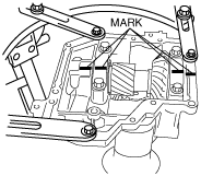
4. Make alignment marks on the bearing cap and drive gear case.
bawuua00000174
|
5. Remove the bearing cap.
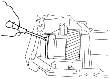
6. Insert a flathead screwdriver into spacer notch and remove the adjustment shim.
bawuua00000175
|
bawuua00000176
|
7. Remove the spacer.
bawuua00000177
|
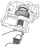
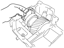
8. Remove the drive gear component.
bawuua00000178
|
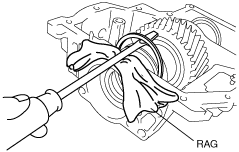
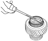
9. Using a tape-wrapped flathead screwdriver, remove the oil seal (LH outer).
bawuua00000549
|
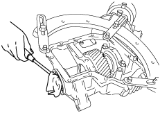
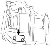
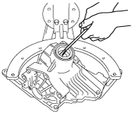
10. Insert a flathead screwdriver in the direction of the arrow and tap the oil seal (LH inner) to remove it.
bawuua00000550
|
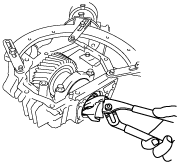
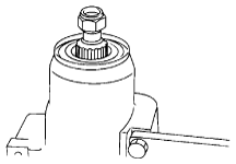
11. Using a tape-wrapped pliers, remove the oil seal (RH outer).
bawuua00000551
|
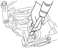
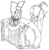
12. Insert a flathead screwdriver in the direction of the arrow and tap the oil seal (RH inner) to remove it.
bawuua00000552
|
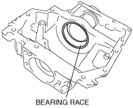
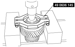
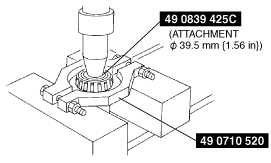
13. Using the SST, remove the bearing outer race (LH).
bawuua00000182
|
bawuua00000183
|
bawuua00000184
|
14. Remove the baffle plate.
bawuua00000185
|
15. Using the SST, remove the bearing (RH).
bawuua00000186
|
16. Using a flathead screwdriver, deform the bearing roller guide (LH) and remove it.
bawuua00000187
|
17. Using the SST, remove the bearing inner race (LH).
bawuua00000188
|
Front Carrier Component Disassembly
bawuua00000554
|
|
1
|
Side cover
|
|
2
|
Side cover
|
|
3
|
Ring gear lockbolt
|
|
4
|
Bearing cap
|
|
5
|
Tubular pin
|
|
6
|
Ring gear component
|
|
7
|
Adjustment shim
|
|
8
|
Spacer
|
|
9
|
Bearing outer race (side)
|
|
10
|
Bearing (side)
|
|
11
|
Ring gear
|
|
12
|
Ring gear shaft
|
|
13
|
Locknut
|
|
14
|
Washer
|
|
15
|
Companion flange
|
|
16
|
Oil seal
|
|
17
|
Drive pinion gear
|
|
18
|
Bearing (rear)
|
|
19
|
Distance piece
|
|
20
|
Bearing (front)
|
|
21
|
Spacer
|
|
22
|
Bearing outer race (front)
|
|
23
|
Bearing outer race (rear)
|
Front Carrier Component Disassembling Procedure
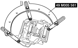
1. Install the front carrier component to the SST.
bawuua00000190
|
2. Make alignment marks on the bearing caps and front carrier.
bawuua00000192
|
3. Remove the bearing caps and tubular pins.
4. Remove the side cover.
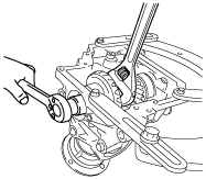
5. Using a suitable wrench, secure the ring gear shaft, and remove the ring gear lockbolt.
bawuua00000193
|
6. Using the SST, secure the companion flange, and remove the locknut and washer.
bawuua00000546
|
7. Using the SST, remove the companion flange.
bawuua00000536
|
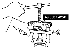
8. Using the SSTs, remove the ring gear component.
bawuua00000196
|
9. Remove the adjustment shims and spacer.
10. Install an appropriate nut to the drive pinion to prevent the thread from being damaged.
bawuua00000537
|
11. Lightly tap the drive pinion using a copper hammer and remove the drive pinion gear.
12. Using a flathead screwdriver, remove the oil seal.
bawuua00000198
|
13. Remove the bearing (rear) and distance piece.
14. Using the SST, remove the bearing (front).
bawuua00000199
|
15. Remove the spacer.
16. Attach the brass stick to the notch, tap the race end lightly and evenly, then remove the bearing outer races.
bawuua00000200
|
bawuua00000201
|
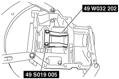
17. Using the SSTs, remove the bearing (side) (opposite ring gear side).
bawuua00000202
|
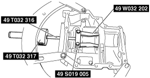
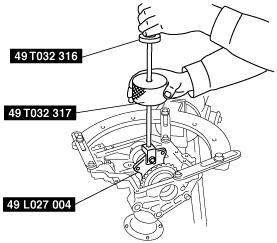
18. Using a SST, remove the bearing (side) (ring gear side) together with ring gear.
bawuua00000203
|