 |
bawuua00000086
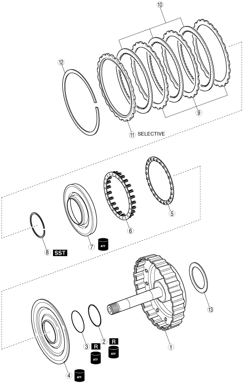
C2 CLUTCH COMPONENT ASSEMBLY
id051700501700
Components
bawuua00000086
|
|
1
|
Intermediate shaft
|
|
2
|
O-ring
|
|
3
|
O-ring
|
|
4
|
C2 clutch piston
|
|
5
|
Spring retainer
|
|
6
|
Piston return spring
|
|
7
|
C2 clutch balancer
|
|
8
|
Snap ring
|
|
9
|
Driven plate
|
|
10
|
Drive plate
|
|
11
|
Retaining plate
|
|
12
|
Snap ring
|
|
13
|
Thrust bearing
|
Assembly Procedure
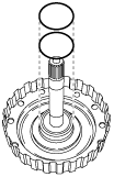
1. Apply ATF to the new O-rings and the intermediate shaft.
2. Install the O-rings to the intermediate shaft.
bawuua00000087
|
O-ring size
|
|
Inner diameter |
Thickness |
|---|---|---|
|
Upper
|
51.90 {2.043}
|
1.60 {0.0630}
|
|
Lower
|
50.40 {1.984}
|
2.62 {0.1031}
|
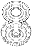
3. Apply ATF to the sliding surface of the C2 clutch piston.
4. Install the C2 clutch piston to the intermediate shaft.
bawuua00000088
|
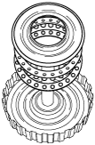
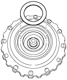
5. Apply ATF to the seal on the clutch balancer and sliding surface.
6. Install the spring retainer, return spring and the clutch balancer to the intermediate shaft.
bawuua00000089
|
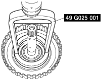
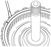
7. Place the SST on the clutch balancer and compress the return spring with a press.
bawuua00000090
|
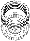
8. Install the snap ring into the groove using snap ring pliers.
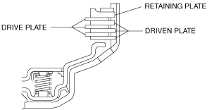
9. Install the driven plates, drive plates and the retaining plate in the following order to the intermediate shaft as shown in the figure.
bawuua00000091
|
bawuua00000092
|
10. Using a flathead screwdriver, install the snap ring into the groove.
bawuua00000093
|
11. Apply ATF to the thrust bearing.
12. Install the thrust bearing to the intermediate shaft.
bawuua00000094
|
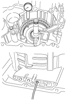
13. Install the intermediate shaft on the transaxle case and set a dial indicator as shown in the figure.
bawuua00000095
|
14. Apply compressed air as shown in the figure and measure the C2 clutch piston stroke.
Retaining plate size
|
Identification mark |
Thickness (mm {in}) |
|---|---|
|
1
|
2.5 {0.0984}
|
|
2
|
2.6 {0.102}
|
|
3
|
2.7 {0.106}
|
|
4
|
2.8 {0.110}
|
|
A
|
2.85 {0.112}
|
|
5
|
2.9 {0.114}
|
|
B
|
2.95 {0.116}
|
|
6
|
3.0 {0.118}
|
|
C
|
3.05 {0.120}
|
|
7
|
3.1 {0.122}
|
|
8
|
3.2 {0.126}
|