 |
bawwza00000001
AUTOMATIC TRANSAXLE DISASSEMBLY
id051700502100
Precaution
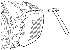
1. Handle electronic parts with care
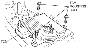
2. Prevent foreign matter from penetrating
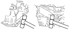
3. Prevent scratching
4. Prevent incorrect installation and lack of or missing parts
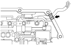
5. Wash parts and apply oil
6. Handling ATF with care
Disassembly
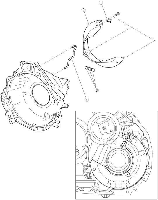
Components
bawwza00000001
|
|
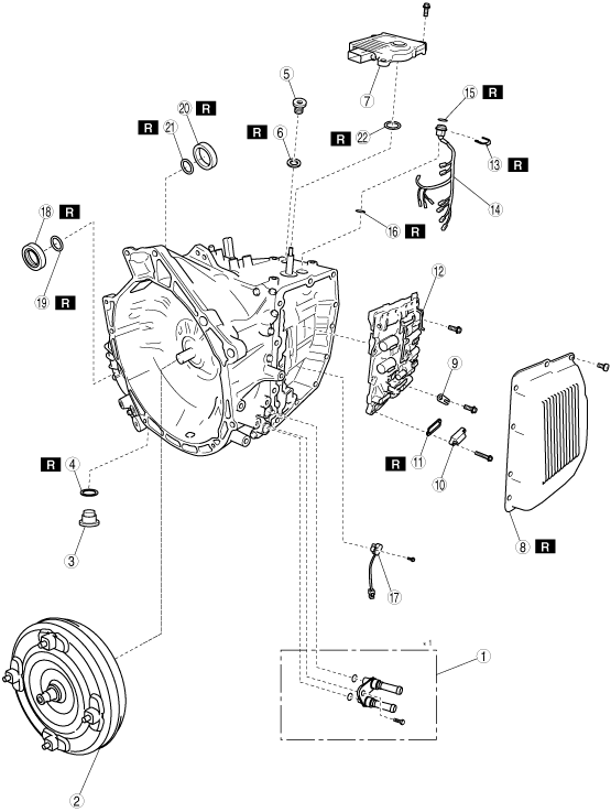
1
|
Oil pipe and O-ring
|
|
2
|
Torque converter
|
|
3
|
Drain plug
|
|
4
|
Gasket
|
|
5
|
Filler plug
|
|
6
|
O-ring
|
|
7
|
TCM
|
|
8
|
Control valve body cover
|
|
9
|
Lock plate
|
|
10
|
Suction cover
|
|
11
|
Gasket
|
|
12
|
Control valve body component
|
|
13
|
Coupler component lock plate
|
|
14
|
Coupler component
|
|
15
|
O-ring
|
|
16
|
Gasket
|
|
17
|
Input/turbine speed sensor
|
|
18
|
Oil seal (converter housing side)
|
|
19
|
O-ring (converter housing side) (2WD)
|
|
20
|
Oil seal (transaxle case side)
|
|
21
|
O-ring (transaxle case side)
|
|
22
|
Oil seal (manual shaft)
|
bawuua00000280
|
|
1
|
Breather pipe
|
|
2
|
O-ring
|
|
3
|
Transaxle case gasket
|
|
4
|
Gasket
|
|
5
|
Gasket
|
|
6
|
Oil Pump component
|
|
7
|
Oil strainer
|
|
8
|
C3 clutch component
|
|
9
|
Front planetary gear component and input shaft
|
|
10
|
Brake band anchor bolt
|
|
11
|
B1 brake band
|
|
12
|
Snap ring
|
|
13
|
Brake piston cover
|
|
14
|
B1 brake piston
|
|
15
|
Piston return spring
|
|
16
|
Thrust bearing
|
|
17
|
Bearing race
|
|
18
|
C1 clutch component
|
|
19
|
Thrust bearing
|
|
20
|
Bearing race
|
|
21
|
Sun gear input drum
|
|
22
|
Counter gear component
|
|
23
|
Differential component
|
|
24
|
Lock washer
|
|
25
|
Counter drive gear
|
|
26
|
Vehicle speed sensor (VSS)
|
|
27
|
Spacer
|
|
28
|
Snap Ring
|
|
29
|
Rear planetary gear component and one-way clutch component
|
|
30
|
Bearing race
|
|
31
|
Thrust bearing
|
|
32
|
Bearing race
|
|
33
|
Snap ring
|
|
34
|
Retaining plate
|
|
35
|
Drive plate
|
|
36
|
Driven plate
|
|
37
|
Retaining plate
|
|
38
|
C2 clutch component
|
|
39
|
Thrust bearing
|
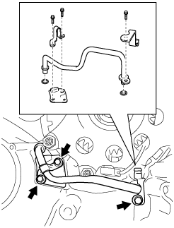
bawuua00000281
|
|
1
|
Tube clamp
|
|
2
|
Oil reservoir lock plate
|
|
3
|
Magnet
|
|
4
|
Oil pipe
|
bawuua00000282
|
|
1
|
Stud bolt
|
|
2
|
Detent spring cover
|
|
3
|
Detent spring
|
|
4
|
Parking pawl shaft
|
|
5
|
Pawl return spring
|
|
6
|
Spring guide sleeve
|
|
7
|
Torsion spring
|
|
8
|
Parking pawl bracket
|
|
9
|
Parking pawl
|
|
10
|
Manual valve lever
|
|
11
|
Parking rod
|
|
12
|
Parking pin
|
|
13
|
Pipe clamp
|
|
14
|
Transaxle case No.1 plate
|
|
15
|
Wiring harness clip
|
|
16
|
Oil cooler outlet tube
|
|
17
|
O-ring
|
|
18
|
Seal ring
|
|
19
|
Transaxle case plate No.2
|
|
20
|
Transaxle case plate No.3
|
Disassembly procedure
1. Remove the oil pipes and O-rings. (Refer to Workshop Manual.)
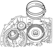
2. Remove the torque converter.
bawuua00000283
|
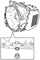
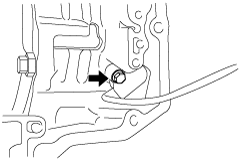
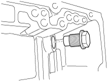
3. Remove the drain plug and gasket.
bawuua00000284
|
4. Drain the ATF.
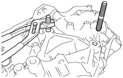
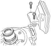
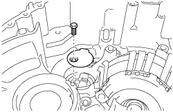
5. Remove the stud bolts.
bawuua00000285
|
bawuua00000286
|
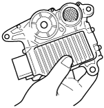
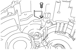
6. Remove the TCM.
bawuua00000287
|
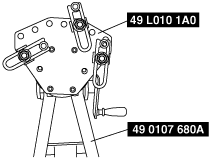
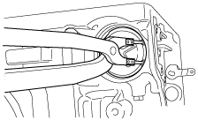
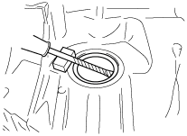
7. Set the SST as shown in the figure.
bawuua00000288
|
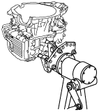
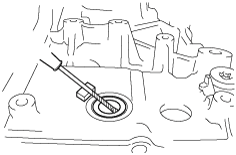
8. Install the SST to the position where the transaxle stud bolts were removed.
bawuua00000289
|
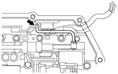
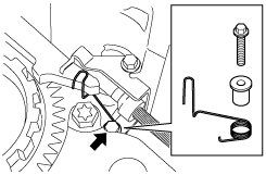
9. Remove the control valve body cover installation bolt.
bawuua00000290
|
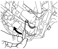
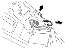
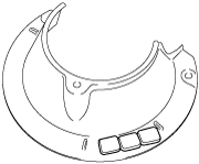
10. Using a plastic hammer, tap the control valve body cover to remove it.
bawuua00000291
|
bawuua00000292
|
bawuua00000293
|
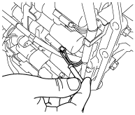
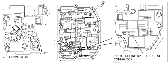
11. Disconnect the solenoid connectors, VSS connector and the input/turbine speed sensor connector.
bawuua00000294
|
12. Disconnect the coupler component from the clamp.
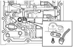
13. Remove the lock plate, and pull out the TFT sensor from the control valve body.
bawuua00000295
|
14. Remove the O-ring from the TFT sensor.
15. Fix the coupler component with tape to the transaxle case as shown in the figure.
bawuua00000296
|
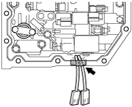
16. Remove the VSS connector and input/turbine speed sensor connector from the solenoid clamp.
bawuua00000297
|
17. Secure the VSS wiring harness and input/turbine speed sensor wiring harness with tape to the transaxle case as shown in the figure.
bawuua00000298
|
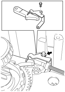
18. Remove the suction cover and the gasket.
bawuua00000299
|
19. Remove the control valve body installation bolts.
bawuua00000300
|
20. Disconnect the manual valve link and remove the control valve body component.
bawuua00000301
|
21. Remove the coupler component lock plate.
bawuua00000302
|
22. Remove the coupler component from the transaxle case.
23. Remove the O-ring and the gasket from the coupler component.
bawuua00000303
|
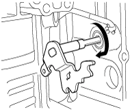
24. Remove the input/turbine speed sensor.
bawuua00000304
|
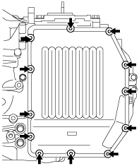
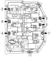
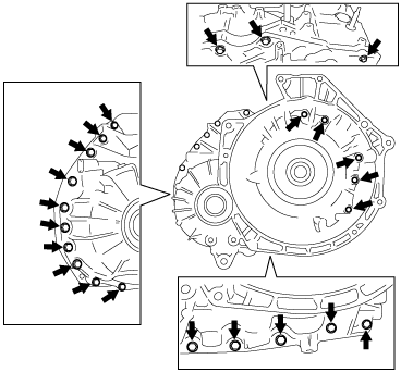
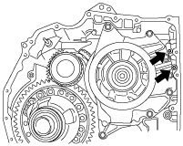
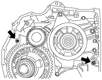
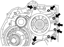
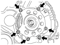
25. Remove the bolts as shown in the figure.
bawuua00000305
|
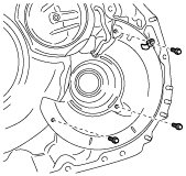
26. Using a plastic hammer, tap the converter housing to remove it.
bawuua00000306
|
27. Remove the transaxle case gaskets as shown in the figure.
bawuua00000307
|
28. Remove the gaskets as shown in the figure.
bawuua00000308
|
29. Remove the tube clamp and the oil reservoir lock plate.
bawuua00000309
|
30. Remove the magnets from the oil reservoir lock plate.
bawuua00000310
|
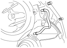
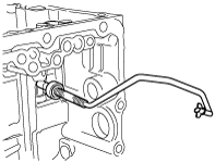
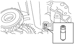
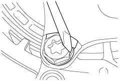
31. Using a flathead screwdriver, remove the oil pipe.
bawuua00000311
|
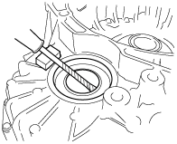
32. Remove the oil seal lip using a razor.
33. Using a tape-wrapped flathead screwdriver, remove the oil seal (converter housing side).
bawuua00000312
|
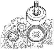
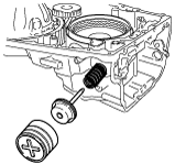
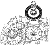
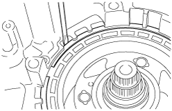
34. Remove the oil pump component.
bawuua00000313
|
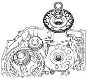
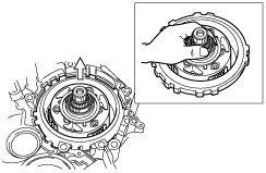
35. Remove the oil seal and the oil strainer from the oil pump component.
bawuua00000314
|
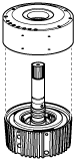
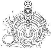
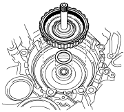
36. Remove the C3 clutch component, input shaft and the front planetary gear component.
bawuua00000315
|
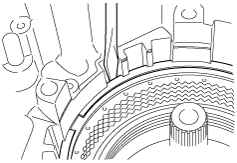
37. Remove the C3 clutch component from the input shaft and the front planetary gear component.
bawuua00000316
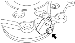
|
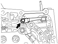
38. Remove the brake band anchor bolt.
bawuua00000317
|
39. Remove B1 the brake band.
bawuua00000318
|
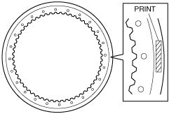
40. Inspect the lining of the brake band.
bawuua00000319
|
41. Remove the snap ring using snap ring pliers.
bawuua00000320
|
42. Remove the brake piston cover, B1 brake piston and the piston return spring.
bawuua00000321
|
43. Remove the thrust bearing, bearing race and the C1 clutch component.
bawuua00000322
|
44. Remove the thrust bearing, bearing race and the sun gear input drum.
bawuua00000323
|
45. Remove the detent spring cover and detent spring.
bawuua00000324
|
46. Remove the pawl return spring and the parking pawl shaft.
bawuua00000325
|
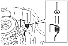
47. Remove the torsion spring and the spring guide sleeve.
bawuua00000326
|
48. Remove the parking pawl and the parking pawl bracket.
bawuua00000327
|
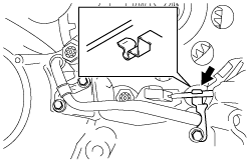
49. Disconnect the parking rod from the manual valve lever.
bawuua00000328
|
50. Remove the manual valve lever from the transaxle case.
bawuua00000329
|
51. Remove the parking rod from the transaxle case.
bawuua00000330
|
52. Remove the parking pin from the transaxle case.
bawuua00000331
|
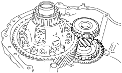
53. Remove the counter gear component.
bawuua00000332
|
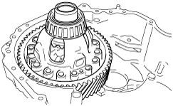
54. Remove the differential component.
bawuua00000333
|
55. Disconnect the VSS wiring harness from the tube wiring clamp.
bawuua00000334
|
56. Remove the pipe clamp, transaxle case No.1 plate, wiring harness clip and the oil cooler outlet tube.
bawuua00000335
|
57. Remove the O-rings from the oil cooler outlet tube.
58. Using a flathead screwdriver and a hammer, pry back the crimp on the lockwashers.
bawuua00000336
|
59. Remove the lockwashers, washers and the counter drive gear.
bawuua00000337
|
60. Remove the VSS and spacer from the counter drive gear.
bawuua00000338
|
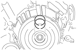
61. Using a flathead screwdriver, remove the snap ring.
bawuua00000339
|
62. Remove the rear planetary gear component and the one-way clutch.
bawuua00000340
|
63. Remove the thrust bearing and the bearing races.
bawuua00000341
|
64. Using a flathead screwdriver, remove the snap ring.
bawuua00000342
|
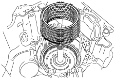
65. Remove the retaining plates, drive and driven plates.
bawuua00000343
|
66. Inspect the lining of all drive plates.
bawuua00000344
|
67. Remove the C2 clutch component and the thrust bearing.
bawuua00000345
|
68. Remove the seal rings from the transaxle case.
bawuua00000346
|
69. Remove the transaxle case plate No.2.
bawuua00000347
|
70. Remove the transaxle case plate No.3.
bawuua00000348
|
71. Remove the oil seal lip using a razor.
72. Using a tape-wrapped flathead screwdriver, remove the oil seal (transaxle case side).
bawuua00000349
|
73. Using a tape-wrapped flathead screwdriver, remove the oil seal (manual shaft).
bawuua00000350
|