 |
bawuua00000412
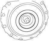
AUTOMATIC TRANSAXLE ASSEMBLY
id051700502200
Assembly
Bearing and race locations
bawuua00000412
|
|
|
|
1 |
2 |
3 |
4 |
5 |
6 |
7 |
8 |
9 |
10 |
11 |
|---|---|---|---|---|---|---|---|---|---|---|---|---|
|
Thrust washer (mm {in})
|
Outer
|
64.0 {2.52}
|
101.0 {3.98}
|
85.0 {3.35}
|
—
|
—
|
—
|
79.8 {3.14}
|
104.2 {4.10}
|
—
|
—
|
—
|
|
Inner
|
51.0 {2.01}
|
75.3 {2.96}
|
72.7 {2.86}
|
—
|
—
|
—
|
68.3 {2.69}
|
69.0 {2.72}
|
—
|
—
|
—
|
|
|
Bearing race (front) (mm {in})
|
Outer
|
—
|
—
|
—
|
—
|
—
|
—
|
—
|
—
|
—
|
43.7 {1.72}
|
—
|
|
Inner
|
—
|
—
|
—
|
—
|
—
|
—
|
—
|
—
|
—
|
25.6 {1.01}
|
—
|
|
|
Bearing (mm {in})
|
Outer
|
—
|
—
|
—
|
61.3 {2.41}
|
52.6 {2.07}
|
45.6 {1.80}
|
—
|
—
|
48.7 {1.92}
|
43.8 {1.72}
|
75.0 {2.95}
|
|
Inner
|
—
|
—
|
—
|
43.7 {1.72}
|
39.2 {1.54}
|
33.2 {1.31}
|
—
|
—
|
35.0 {1.38}
|
24.25 {0.9547}
|
50.5 {1.99}
|
|
|
Bearing race (rear) (mm {in})
|
Outer
|
—
|
—
|
—
|
68.8 {2.71}
|
48.5 {1.91}
|
47.0 {1.85}
|
—
|
—
|
45.6 {1.80}
|
41.7 {1.64}
|
—
|
|
Inner
|
—
|
—
|
—
|
46.9 {1.85}
|
38.1 {1.50}
|
35.2 {1.39}
|
—
|
—
|
33.2 {1.31}
|
24.2 {0.953}
|
—
|
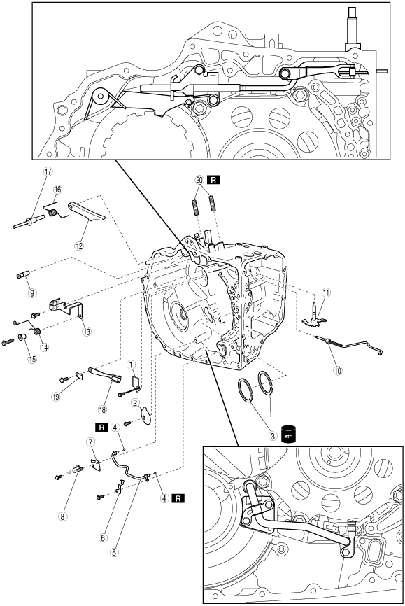
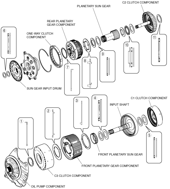
Components
bawuua00000413
|
|
1
|
Transaxle case plate No.3
|
|
2
|
Transaxle case plate No.2
|
|
3
|
Seal ring
|
|
4
|
O-ring
|
|
5
|
Oil cooler outlet tube
|
|
6
|
Wiring harness clip
|
|
7
|
Transaxle case No.1 plate
|
|
8
|
Pipe clamp
|
|
9
|
Parking pin
|
|
10
|
Parking rod
|
|
11
|
Manual valve lever
|
|
12
|
Parking pawl
|
|
13
|
Parking pawl bracket
|
|
14
|
Torsion spring
|
|
15
|
Spring guide sleeve
|
|
16
|
Pawl return spring
|
|
17
|
Parking pawl shaft
|
|
18
|
Detent spring
|
|
19
|
Detent spring cover
|
|
20
|
Stud bolt
|
bawuua00000414
|
|
1
|
Oil pipe
|
|
2
|
Magnet
|
|
3
|
Oil reservoir lock plate
|
|
4
|
Tube clamp
|
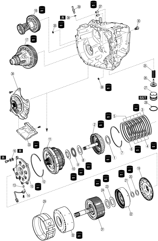
bawuua00000415
|
|
1
|
Thrust bearing
|
|
2
|
C2 clutch component
|
|
3
|
Retaining plate
|
|
4
|
Driven plate
|
|
5
|
Drive plate
|
|
6
|
Retaining plate
|
|
7
|
Snap ring
|
|
8
|
Bearing race
|
|
9
|
Thrust bearing
|
|
10
|
Bearing race
|
|
11
|
Rear planetary gear component and one-way clutch component
|
|
12
|
Snap Ring
|
|
13
|
Spacer
|
|
14
|
Vehicle speed sensor (VSS)
|
|
15
|
Counter drive gear
|
|
16
|
Lock washer
|
|
17
|
Differential component
|
|
18
|
Counter gear component
|
|
19
|
Sun gear input drum
|
|
20
|
Bearing race
|
|
21
|
Thrust bearing
|
|
22
|
C1 clutch component
|
|
23
|
Bearing race
|
|
24
|
Thrust bearing
|
|
25
|
Piston return spring
|
|
26
|
B1 brake piston
|
|
27
|
Brake piston cover
|
|
28
|
Snap ring
|
|
29
|
B1 brake band
|
|
30
|
Brake band anchor bolt
|
|
31
|
Front planetary gear component and input shaft
|
|
32
|
C3 clutch component
|
|
33
|
Oil strainer
|
|
34
|
Oil Pump component
|
|
35
|
Gasket
|
|
36
|
Gasket
|
|
37
|
Transaxle case gasket
|
|
38
|
O-ring
|
|
39
|
Breather pipe
|
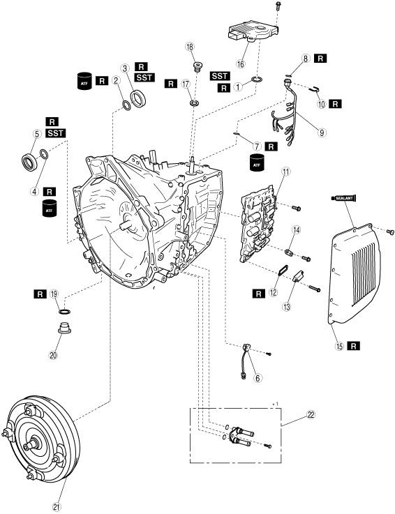
bawwza00000002
|
|
1
|
Oil seal (manual shaft)
|
|
2
|
O-ring (transaxle case side)
|
|
3
|
Oil seal (transaxle case side)
|
|
4
|
O-ring (converter housing side) (2WD)
|
|
5
|
Oil seal (converter housing side)
|
|
6
|
Input/turbine speed sensor
|
|
7
|
Gasket
|
|
8
|
O-ring
|
|
9
|
Coupler component
|
|
10
|
Coupler component lock plate
|
|
11
|
Control valve body component
|
|
12
|
Gasket
|
|
13
|
Suction cover
|
|
14
|
Lock plate
|
|
15
|
Control valve body cover
|
|
16
|
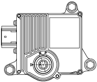
TCM
|
|
17
|
O-ring
|
|
18
|
Filler plug
|
|
19
|
Gasket
|
|
20
|
Drain plug
|
|
21
|
Torque converter
|
|
22
|
Oil pipe and O-ring
|
Assembly Procedure
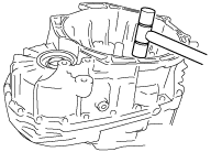
1. Using the SST and a hammer, install a new oil seal to the transaxle case.
bawuua00000417
|
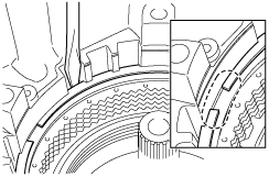
2. Apply ATF to the new seal rings and sliding surface of the transaxle case.
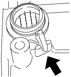
3. Compress the seal rings as shown in the figure. Then install the seal rings in the transaxle case.
bawuua00000418
|
4. Install the transaxle case plate No.3.
bawuua00000419
|
5. Install the transaxle case plate No.2.
bawuua00000420
|
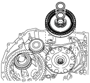
6. Apply ATF or grease to the thrust bearing and install it to the C2 clutch component.
bawuua00000421
|
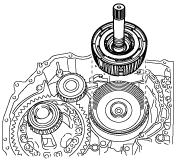
7. Apply ATF to the seal ring and rubbing surface of the C2 clutch component where the bushing is fit.
8. Install the C2 clutch component to the transaxle case.
bawuua00000422
|
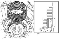
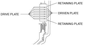
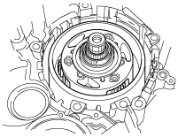
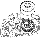
9. Apply ATF to the driven plates, drive plates and retaining plates.
10. Install driven plates, drive plates and the retaining plate in the following order to the transaxle case as shown in the figure.
bawuua00000423
|
bawuua00000424
|
11. Using a flathead screwdriver, install the snap ring in the groove.
bawuua00000425
|
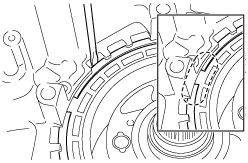
12. Apply ATF to the thrust bearing and the bearing races and install them to the transaxle case.
bawuua00000426
|
13. Apply ATF to each gear and the bushing, and then install the rear planetary gear component to the transaxle case.
bawuua00000427
|
14. Apply ATF to the sliding surface of the one-way clutch.
15. Install the one-way clutch to the transaxle case.
bawuua00000428
|
16. Using a flathead screwdriver, install the snap ring in the groove.
bawuua00000429
|
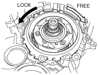
17. While holding the one-way clutch component, inspect that the planetary gear turns to right (clockwise) but does not turn to left (counterclockwise).
bawuua00000430
|
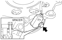
18. Install the VSS and spacer to the counter drive gear.
bawuua00000431
|
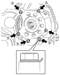
19. Apply ATF to the spline on the counter drive gear and spline on the ring gear.
20. Install the counter drive gear to the transaxle case.
21. Install the new lockwashers and washers with new bolts.
bawuua00000432
|
22. Using a flathead screwdriver and a hammer, pry back the crimp locking the lockwashers.
bawuua00000433
|
23. Apply ATF to the new O-rings.
24. Install the O-rings to the oil cooler outlet tube.
25. Install the oil cooler outlet tube, pipe clamp, transaxle case No.1 plate and the wiring harness clip to the converter housing.
bawuua00000434
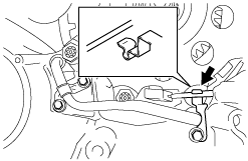
|
26. Connect the VSS wiring harness to the wiring harness clip.
bawuua00000435
|
27. Apply ATF to the bearing and gear of the differential component.
28. Install the differential component to the transaxle case.
bawuua00000436
|
29. Apply ATF to the bearing and gear of the counter gear component.
30. Install the counter gear component to the transaxle case.
bawuua00000437
|
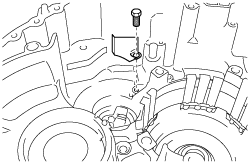
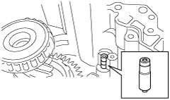
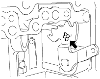
31. Install the parking pin to the transaxle case.
bawuua00000438
|
32. Insert the parking rod to the transaxle case.
bawuua00000439
|
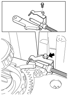
33. Install the manual valve lever to the transaxle case.
bawuua00000440
|
34. Connect the parking rod to the manual valve lever.
bawuua00000441
|
35. Install the parking pawl, parking pawl bracket and the parking rod to the transaxle case.
bawuua00000442
|
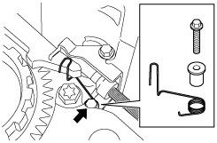
36. Install the spring guide sleeve and the torsion spring.
bawuua00000443
|
37. Install the pawl return spring to the parking pawl shaft.
38. Install the pawl return spring and the parking pawl shaft to the transaxle case.
bawuua00000444
|
39. Install the detent spring cover and detent spring to the transaxle case.
bawuua00000445
|
bawuua00000446
|
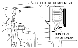
40. Install the sun gear input drum to the transaxle case.
bawuua00000447
|
41. Apply ATF to the bearing race and the thrust bearing, and then install them to the transaxle case.
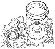
42. Install the C1 clutch component to the transaxle case.
bawuua00000448
|
43. Apply ATF to the bearing race and the thrust bearing, and then install them to the transaxle case.
44. Install the input shaft and the front planetary gear to the transaxle case.
bawuua00000449
|
45. Apply ATF to the bushing of the C3 clutch component.
46. Install the C3 clutch component to the transaxle case.
bawuua00000450
|
bawuua00000451
|
47. Install the B1 brake band to the transaxle case.
bawuua00000452
|
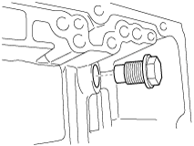
48. Install the brake band anchor bolt to the transaxle case.
bawuua00000453
|
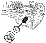
49. Install the piston return spring, B1 brake piston and the brake piston cover to the transaxle case.
bawuua00000454
|
50. Using the SST, press the brake piston cover into the position where the snap ring groove is visible.
bawuua00000455
|
51. Apply ATF to the oil seal.
52. Install the oil strainer and the oil seal to the oil pump component.
bawuua00000456
|
53. Apply ATF to each rubbing surface of the oil pump component.
54. Install the oil pump component to the transaxle case.
bawuua00000457
|
55. Verify that the input shaft turns smoothly.
bawuua00000458
|
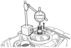
56. Using a dial indicator, measure the input shaft end play.
bawuua00000459
|
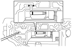
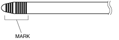
57. Put a mark on the piston rod at the point where it intersects with the case.
bawuua00000460
|
58. Measure the stroke between the transaxle case and the mark on the piston rod when applying compressed air into the oil hole as shown in the figure.
bawuua00000461
|
Piston rod size
|
Identification mark |
Length (mm {in}) |
|---|---|
|
—
|
102.80 {4.0473}
|
|
1
|
103.05 {4.0571}
|
|
2
|
103.30 {4.0669}
|
|
3
|
103.55 {4.0768}
|
|
4
|
103.80 {4.0866}
|
|
5
|
104.05 {4.0965}
|
|
6
|
104.30 {4.1063}
|
|
7
|
104.55 {4.1161}
|
|
8
|
104.80 {4.1260}
|
|
9
|
105.05 {4.1358}
|
|
10
|
105.30 {4.1457}
|
bawuua00000462
|
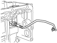
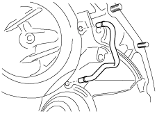
59. Install the differential gear lube apply tube to the converter housing.
bawuua00000463
|
60. Install the magnets to the oil reservoir lock plate.
bawuua00000464
|
61. Install the oil reservoir lock plate and the tube clamp to the converter housing.
bawuua00000465
|
62. Apply ATF to the new gaskets.
63. Install the gaskets to the transaxle case as shown in the figure.
bawuua00000466
|
64. Apply ATF to the new transaxle case gaskets.
65. Install the transaxle case gaskets to the transaxle case as shown in the figure.
bawuua00000467
|
66. Remove any packing material and be careful not to get oil on the contact surface of the transaxle case and the converter housing.
67. Clean the contact surface of the transaxle case and the converter housing and the bolt holes.
68. Apply ATF to a O-ring of the oil pump.
69. Apply sealant to the converter housing as shown in the figure.
bawuua00000468
|
70. Install the converter housing to the transaxle case.
bawuua00000469
|
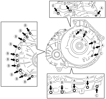
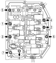
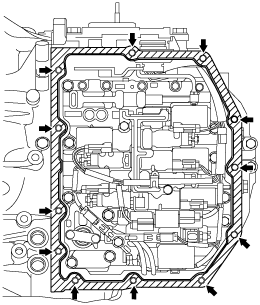
71. Temporarily tighten the bolts by hand as shown in the figure.
bawuua00000470
|
|
Bolt number |
Bolt size |
Length (measured from below the head) (mm {in}) |
|---|---|---|
|
A
|
M8 × 1.25
|
30 {1.18}
|
|
B
|
M8 × 1.25
|
35 {1.38}
|
|
C
|
M8 × 1.25
|
39 {1.54}
|
|
D
|
M10 × 1.25
|
25 {0.984}
|
|
E
|
M10 × 1.25
|
40 {1.57}
|
72. Tighten the bolts.
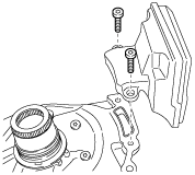
73. Install the input/turbine speed sensor to the transaxle case.
bawuua00000471
|
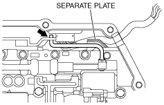
74. Apply ATF to a new gasket as shown in the figure.
bawuua00000472
|
75. Install the gasket to the coupler component.
76. Install a new O-ring to the coupler component.
77. Install the coupler component to the transaxle case.
78. Install a new coupler component lock plate.
bawuua00000473
|
79. Connect the manual valve link and install the control valve body component.
bawuua00000474
|
80. Temporarily install the control valve body component with the bolts.
bawuua00000475
|
81. Temporarily install the suction cover and a new gasket with the bolts.
bawuua00000476
|
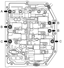
82. Tighten the bolts in the order shown in the figure.
bawuua00000477
|
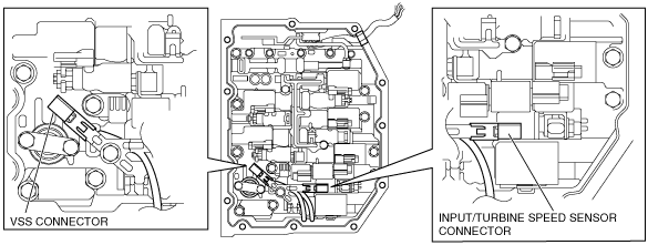
83. Install the connector of the VSS and input/turbine speed sensor to the solenoid clamp.
bawuua00000478
|
bawuua00000479
|
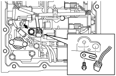
84. Apply ATF to a new O-ring and install it on the TFT sensor.
85. Install the TFT sensor with the lock plate and a bolt to the control valve body component as shown in the figure.
bawuua00000480
|
86. Connect the solenoid connectors, VSS connector and the input/turbine speed sensor connector.
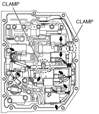
87. Connect the coupler component to the clamps.
bawuua00000481
|
88. Clean sealant and oil off the contact surface of the transaxle case with the control valve body cover and the bolt holes.
bawuua00000482
|
89. Clean oil off the contact surface of the new control valve body cover with the transaxle case.
90. Apply sealant to the new control valve body cover as shown in the figure.
bawuua00000483
|
91. Install the new control valve body cover with new seal bolts.
bawuua00000484
|
92. Inspect the condition of connector pin of the coupler component (foreign material, bent/broken pins) and O-ring.
bawuua00000485
|
93. Align the transaxle case and the coupler component connector.
bawuua00000486
|
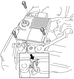
94. Be sure to match the position of the TCM marking.
bawuua00000487
|
95. Verify the correct positioning of the TCM and coupler component.
bawuua00000488
|
96. Install the TCM to the transaxle case.
97. Install the double nutted stud bolts to the transaxle case.
bawuua00000489
|
98. Remove the double nutted from the stud bolt.
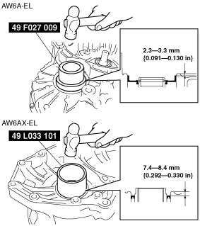
99. Using the SST and a hammer, tap a new oil seal so that the specified oil seal position is obtained.
Transaxle Case Side
bawuua00000490
|
Converter Housing Side
bawuua00000491
|
100. Install a new gasket and the drain plug.
bawuua00000492
|
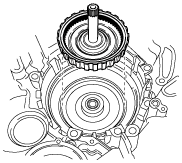
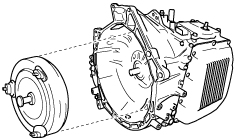
101. Using a flathead screwdriver, position the drive gear on the oil pump component in the center. Then install the torque converter component to the transaxle.
bawuua00000493
|
102. To ensure that the torque converter is installed accurately, measure distance A between the end of the torque converter and the end of the converter housing.
bawuua00000494
|
103. Install the O-rings and oil pipes. (Refer to the Workshop Manual.)
104. Add the ATF.