 |
bawuua00000012
AUTOMATIC TRANSAXLE INSPECTION
id051700502300
B2 Brake Inspection
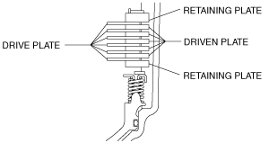
1. Apply ATF to the driven plates, drive plates and retaining plates.
2. Install driven plates, drive plates and the retaining plate in the following order to the transaxle case as shown in the figure.
bawuua00000012
|
bawuua00000013
|
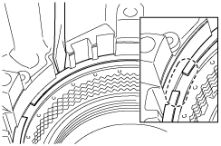
3. Using a flathead screwdriver, install the snap ring into the groove.
bawuua00000014
|
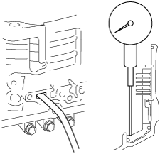
4. Set a dial indicator as shown in the figure.
bawuua00000015
|
5. While applying compressed air into the oil passage as shown in the figure, measure the B2 brake clearance and inspect the piston moves smoothly.
Retaining plate size
|
Identification mark |
Thickness (mm {in}) |
|---|---|
|
47
|
4.7 {0.185}
|
|
48
|
4.8 {0.189}
|
|
49
|
4.9 {0.193}
|
|
50
|
5.0 {0.197}
|
|
51
|
5.1 {0.201}
|
|
52
|
5.2 {0.205}
|
|
53
|
5.3 {0.209}
|
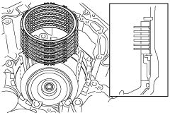
6. Using a flathead screwdriver, remove the snap ring.
bawuua00000014
|
7. Remove the retaining plates, drive and driven plates.
bawuua00000012
|