 |
ac9wzw00002402
ON-BOARD DIAGNOSTIC TEST [MZI-3.7 (PCM CONNECTOR (3 TYPES))]
id0102e4801000
DTC Reading Procedure
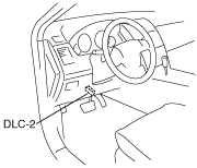
1. Connect the M-MDS to the DLC-2.
ac9wzw00002402
|
2. After the vehicle is identified, select the following items from the initial screen of the M-MDS.
3. Then, select the “Retrieve CMDTCs” and perform procedures according to directions on the M-MDS screen.
4. Verify the DTC according to the directions on the M-MDS screen.
5. After completion of repairs, clear all DTCs stored in the PCM, while referring to “AFTER REPAIR PROCEDURE“.
Pending Trouble Code Access Procedure
1. Connect the M-MDS to the DLC-2.
ac9wzw00002402
|
2. After the vehicle is identified, select the following items from the initial screen of the M-MDS.
3. Then, select the “Retrieve CMDTCs” and perform procedures according to directions on the M-MDS screen.
4. Retrieve the pending trouble codes according to the directions on the M-MDS screen.
Freeze Frame PID Data Access Procedure
1. Connect the M-MDS to the DLC-2.
ac9wzw00002402
|
2. After the vehicle is identified, select the following items from the initial screen of the M-MDS.
3. Then, select the “Retrieve CMDTCs” and perform procedures according to directions on the M-MDS screen.
4. Retrieve the freeze frame PID data according to the directions on the M-MDS screen.
On-Board System Readiness Tests Access Procedure
1. Connect the M-MDS to the DLC-2.
ac9wzw00002402
|
2. After the vehicle is identified, select the following items from the initial screen of the M-MDS.
3. Then, select the “***SUP” and “**EVAL” PIDs in the PID selection screen.
4. Monitor those PIDs and check it system monitor is completed.
PID/DATA Monitor and Record Procedure
1. Connect the M-MDS to the DLC-2.
ac9wzw00002402
|
2. After the vehicle is identified, select the following items from the initial screen of the M-MDS.
3. Select the PID from the PID table.
4. Verify the test results according to detections on the screen.
PID/Data Monitor Table
The Mazda Modular Diagnostic System (M-MDS)
|
PID Name |
Description |
Unit |
|||
|---|---|---|---|---|---|
|
AAT
|
Ambient air temperature
|
°C
|
°F
|
||
|
AC_PRES
|
Refrigerant pressure sensor
|
V
|
|||
|
kPa
|
psi
|
Bar
|
|||
|
AC_REQ
|
A/C request signal
|
Off/On
|
|||
|
ACCS
|
A/C relay
|
Off/On
|
|||
|
ALTF
|
Generator field coil control duty value
|
%
|
|||
|
APP
|
Accelerator pedal position
|
%
|
|||
|
APP1
|
APP sensor No.1
|
%
|
|||
|
V
|
|||||
|
APP2
|
APP sensor No.2
|
%
|
|||
|
V
|
|||||
|
ARPMDES
|
Target engine speed
|
RPM
|
|||
|
AXLE
|
Axle ratio
|
—
|
|||
|
BARO
|
Barometric pressure
|
kPa
|
psi
|
Bar
|
|
|
BOO
|
Brake switch
|
Off/On
|
|||
|
BPA
|
Brake pressure applied switch
|
Off/On
|
|||
|
CATT11_DSD
|
Estimated catalytic converter temperature (RH)
|
°C
|
°F
|
||
|
CATT21_DSD
|
Estimated catalytic converter temperature (LH)
|
°C
|
°F
|
||
|
CHRGLP
|
Generator warning light
|
Off/On
|
|||
|
CHT
|
CHT sensor
|
°C
|
°F
|
||
|
V
|
|||||
|
ECT
|
Engine coolant temperature
|
°C
|
°F
|
||
|
EQ_RAT11
|
Equivalence ratio (lambda) A/F sensor (RH)
|
—
|
|||
|
EQ_RAT11_DSD
|
Desired equivalence ratio (lambda)
|
—
|
|||
|
EQ_RAT12
|
Equivalence ratio (lambda) HO2S (RH)
|
—
|
|||
|
ETC_ACT
|
Electronic throttle control actual
|
°
|
|||
|
ETC_DSD
|
Electronic throttle control desired
|
%
|
|||
|
°
|
|||||
|
EVAPCP
|
Purge solenoid valve duty value
|
%
|
|||
|
EVAPCV
|
CV solenoid valve
|
Off/On
|
|||
|
FAN_DUTY
|
Cooling fan control
|
%
|
|||
|
FCL
|
Fuel cap warning light
|
Off/On
|
|||
|
FLI
|
Fuel level
|
%
|
|||
|
FP
|
Fuel pump relay
|
Off/On
|
|||
|
FPM
|
Fuel pump monitor
|
Off/On
|
|||
|
FTP
|
Fuel tank pressure sensor
|
V
|
|||
|
FUELSYS
|
Fuel system loop status (RH)
|
OL/CL/OL-Drive/OL-Fault/CL-Fault
|
|||
|
GENVDSD
|
Generator voltage desired
|
V
|
|||
|
HTR11
|
A/F sensor heater (RH)
|
Off/On
|
|||
|
%
|
|||||
|
HTR12
|
HO2S heater (RH)
|
Off/On
|
|||
|
%
|
|||||
|
HTR21
|
A/F sensor heater (LH)
|
Off/On
|
|||
|
HTR22
|
HO2S heater (LH)
|
Off/On
|
|||
|
IAT
|
IAT sensor
|
°C
|
°F
|
||
|
V
|
|||||
|
INGEAR
|
Load/no load condition
|
Off/On
|
|||
|
INJ_PWR
|
Injector power monitor
|
V
|
|||
|
IVS
|
CTP condition
|
Off Idle/Idle
|
|||
|
KNOCKR
|
Knocking retard
|
°
|
|||
|
LOAD
|
Engine load
|
%
|
|||
|
LONGFT1
|
Long term fuel trim (RH)
|
%
|
|||
|
LONGFT2
|
Long term fuel trim (LH)
|
%
|
|||
|
MAF
|
MAF sensor
|
g/s
|
|||
|
V
|
|||||
|
MIL_DIS
|
Travelled distance since the MIL illuminated
|
km
|
|||
|
O2S11
|
A/F sensor (RH)
|
V
|
|||
|
O2S12
|
HO2S (RH)
|
V
|
|||
|
O2S21
|
A/F sensor (LH)
|
V
|
|||
|
O2S22
|
HO2S (LH)
|
V
|
|||
|
PSP
|
PSP switch
|
Low/High
|
|||
|
RO2FT1
|
HO2S fuel trim (RH)
|
—
|
|||
|
RO2FT2
|
HO2S fuel trim (LH)
|
—
|
|||
|
RPM
|
Engine speed
|
RPM
|
|||
|
SC_CANCEL
|
Speed control cancel switch
|
Inactive/Active
|
|||
|
SC_OFF
|
Cruise control OFF switch
|
Inactive/Active
|
|||
|
SC_ON
|
Cruise control ON switch
|
Inactive/Active
|
|||
|
SC_RES
|
Cruise resume switch
|
Inactive/Active
|
|||
|
SC_SET-
|
Cruise coast switch
|
Inactive/Active
|
|||
|
SC_SET+
|
Cruise set/acceleration switch
|
Inactive/Active
|
|||
|
SCCS
|
Speed control command switch
|
V
|
|||
|
SHRTFT1
|
Short term fuel trim (RH)
|
%
|
|||
|
SHRTFT12
|
Short term fuel trim (HO2S) (RH)
|
%
|
|||
|
SHRTFT2
|
Short term fuel trim (LH)
|
%
|
|||
|
SHRTFT22
|
Short term fuel trim (HO2S) (LH)
|
%
|
|||
|
SPARKADV
|
Ignition timing
|
°
|
|||
|
TIRESIZE
|
Tire revolution per mile
|
—
|
|||
|
TP REL
|
Relative throttle position
|
%
|
|||
|
TP1
|
TP sensor No.1
|
%
|
|||
|
V
|
|||||
|
TP2
|
TP sensor No.2
|
%
|
|||
|
V
|
|||||
|
VPWR
|
Battery voltage
|
V
|
|||
|
VSS
|
Vehicle speed
|
KPH
|
|||
|
VT ACT1
|
Actual valve timing (RH)
|
°
|
|||
|
VT ACT2
|
Actual valve timing (LH)
|
°
|
|||
|
VT DIFF1
|
Difference between target and actual valve timing (RH)
|
°
|
|||
|
VT DIFF2
|
Difference between target and actual valve timing (LH)
|
°
|
|||
|
VT DUTY1
|
Oil control valve duty value (RH)
|
%
|
|||
|
VT DUTY2
|
Oil control valve duty value (LH)
|
%
|
|||
|
VT_DSD
|
Desired intake camshaft position
|
°
|
|||
Diagnostic Monitoring Test Results Access Procedure
1. Connect the M-MDS to the DLC-2.
ac9wzw00002402
|
2. After the vehicle is identified, select the following items from the initial screen of the M-MDS.
3. Verify the PID data according to the directions on the screen.
Active Command Modes Procedure
1. Connect the M-MDS to the DLC-2.
ac9wzw00002402
|
2. After the vehicle is identified, select the following items from the initial screen of the M-MDS.
3. Select the simulation items from the PID table.
4. Perform the simulation function, inspect the operations for each parts.