CYLINDER HEAD TEMPERATURE (CHT) SENSOR REMOVAL/INSTALLATION [MZI-3.7]


id0140c3889800

Note
•  Do not reuse the CHT sensor, install a new sensor.

1.  Disconnect the negative battery cable. (See BATTERY REMOVAL/INSTALLATION [MZI-3.7].)

2.  Perform the following procedure for easier access:

1.  Complete the “BEFORE SERVICE PRECAUTION”. (See BEFORE SERVICE PRECAUTION [MZI-3.7].)
2.  Remove the engine cover. (See ENGINE COVER REMOVAL/INSTALLATION [MZI-3.7].)
4.  Remove the throttle body connector. (See INTAKE-AIR SYSTEM REMOVAL/INSTALLATION [MZI-3.7].)
5.  Remove the vacuum hose (to purge solenoid valve). (See QUICK RELEASE CONNECTOR (EMISSION SYSTEM) REMOVAL/INSTALLATION [MZI-3.7].)
6.  Remove the vacuum hose (to master back). (See INTAKE-AIR SYSTEM REMOVAL/INSTALLATION [MZI-3.7].)
7.  Remove the dynamic chamber. (See INTAKE-AIR SYSTEM REMOVAL/INSTALLATION [MZI-3.7].)
9.  Remove the fuel distributor. (See FUEL INJECTOR REMOVAL/INSTALLATION [MZI-3.7].)
10.  Remove the intake manifold. (See INTAKE-AIR SYSTEM REMOVAL/INSTALLATION [MZI-3.7].)

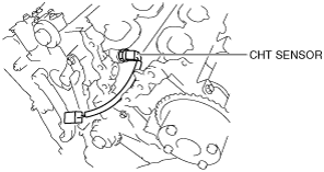
3.  Disconnect the CHT sensor connector.

ac9wzw00002357

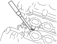
4.  Remove the CHT sensor using the following tools:

•  Deep socket
3/8" Drive 20 mm, 6 point
•  Ratchet handle and torque wrench
3/8" Drive, Compact head type
ac9wzw00001739

5.  Install in the reverse order of removal.

Tightening torque
9—10 N·m {92—101 kgf·cm, 80—88 in·lbf}

6.  Complete the “AFTER SERVICE PRECAUTION”. (See AFTER SERVICE PRECAUTION [MZI-3.7].)