|
1
|
INSPECT WHEEL UNIT SIGNAL FOR OPEN CIRCUIT
• Turn the ignition switch off.
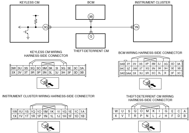
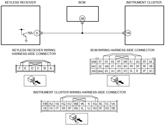
• Disconnect keyless CM, instrument cluster, BCM and theft-deterrent CM connectors.
• Inspect for continuity between keyless CM terminal 3Q (harness-side) and instrument cluster terminal 1N (harness-side).
• Inspect for continuity between keyless CM terminal 3Q (harness-side) and BCM terminal 3B (harness-side).
• Inspect for continuity between keyless CM terminal 3Q (harness-side) and theft-deterrent CM terminal Q (harness-side).
• Is there continuity?
|
Yes
|
Go to the next step.
|
|
No
|
Repair or replace the following wiring harness for an open circuit, then go to Step 7.
― Between keyless CM terminal 3Q and instrument cluster terminal 1N
― Between keyless CM terminal 3Q and BCM terminal 3B
― Between keyless CM terminal 3Q and theft-deterrent CM terminal Q
|
|
2
|
INSPECT WHEEL UNIT SIGNAL FOR SHORT TO POWER
• Turn the ignition switch off.
• Disconnect keyless CM, instrument cluster, BCM and theft-deterrent CM connectors.
• Measure the voltage between keyless CM terminal 3Q (harness-side) and ground.
• Is there B+?
|
Yes
|
Repair or replace the following wiring harness for a short to power, then go to Step 7.
― Between keyless CM terminal 3Q and instrument cluster terminal 1N
― Between keyless CM terminal 3Q and BCM terminal 3B
― Between keyless CM terminal 3Q and theft-deterrent CM terminal Q
|
|
No
|
Go to the next step.
|
|
3
|
INSPECT WHEEL UNIT SIGNAL FOR SHORT TO GROUND
• Turn the ignition switch off.
• Disconnect keyless CM, instrument cluster, BCM and theft-deterrent CM connectors.
• Inspect for continuity between keyless CM terminal 3Q (harness-side) and ground.
• Is there continuity?
|
Yes
|
Repair or replace the following wiring harness for a short to ground, then go to Step 7.
― Between keyless CM terminal 3Q and instrument cluster terminal 1N
― Between keyless CM terminal 3Q and BCM terminal 3B
― Between keyless CM terminal 3Q and theft-deterrent CM terminal Q
|
|
No
|
Go to the next step.
|
|
4
|
INSPECT FOR KEYLESS CM MALFUNCTION
• Turn the ignition switch off.
• Using the M-MDS, perform the DTC inspection for the keyless CM.
• Is any DTCs present?
|
Yes
|
Go to the applicable DTC inspection.
|
|
No
|
Go to the next step.
|
|
5
|
INSPECT FOR BCM MALFUNCTION
• Turn the ignition switch off.
• Using the M-MDS, perform the DTC inspection for the BCM.
• Is any DTCs present?
|
Yes
|
Go to the applicable DTC inspection.
|
|
No
|
Go to the next step.
|
|
6
|
INSPECT FOR THEFT-DETERRENT CM MALFUNCTION
• Turn the ignition switch off.
• Using the M-MDS, perform the DTC inspection for the theft-deterrent CM.
• Is any DTCs present?
|
Yes
|
Go to the applicable DTC inspection.
|
|
No
|
Go to the next step.
|
|
7
|
VERIFY TROUBLESHOOTING COMPLETED
• Turn the ignition switch to the ON position and drive the vehicle at a speed of 25 km/h {15.5 mph} or more.
• Clear the DTC from the memory.
• Is the same DTC present?
|
Yes
|
• Configure the instrument cluster.
• Register the wheel unit ID.
• Go to the next step.
|
|
No
|
Go to the next step.
|
|
8
|
VERIFY AFTER REPAIR PROCEDURE
• Drive the vehicle at a speed of 25 km/h {15.5 mph} or more for 10 min or more.
• Are there any other DTCs present?
|
Yes
|
|
|
No
|
DTC troubleshooting completed.
|