 |
acxuuw00000348
FRONT WHEEL ALIGNMENT
id021100800200
Front wheel alignment [2WD] (Unloaded)*1
|
Item |
Fuel gauge indication |
||||||
|---|---|---|---|---|---|---|---|
|
Empty |
1/4 |
1/2 |
3/4 |
Full |
|||
|
Maximum steering angle
[Tolerance ±3°]
|
Inner
|
38°
|
|||||
|
Outer
|
32°
|
||||||
|
Total toe-in
|
Tire [Tolerance ±4 {0.16}]
|
(mm {in})
|
2 {0.08}
|
||||
|
Rim inner [Tolerance ±3 {0.12}]
|
Vehicle equipped with 18 inch wheel: 1.2 {0.047}
Vehicle equipped with 20 inch wheel: 1.4 {0.055}
|
||||||
|
(degree)
|
0°09′±0°18′
|
||||||
|
Caster angle*2[Tolerance ±1°]
|
3°01′
|
3°02′
|
3°03′
|
3°04′
|
|||
|
Camber angle*2[Tolerance ±1°]
|
−0°19′
|
−0°20′
|
−0°21′
|
||||
|
Steering axis inclination (Reference value)
|
11°31′
|
11°32′
|
11°33′
|
11°34′
|
11°35′
|
||
Front wheel alignment [4WD] (Unloaded)*1
|
Item |
Fuel gauge indication |
||||||
|---|---|---|---|---|---|---|---|
|
Empty |
1/4 |
1/2 |
3/4 |
Full |
|||
|
Maximum steering angle
[Tolerance ±3°]
|
Inner
|
38°
|
|||||
|
Outer
|
32°
|
||||||
|
Total toe-in
|
Tire [Tolerance ±4 {0.16}]
|
(mm {in})
|
2 {0.08}
|
||||
|
Rim inner [Tolerance ±3 {0.12}]
|
Vehicle equipped with 18 inch wheel: 1.2 {0.047}
Vehicle equipped with 20 inch wheel: 1.4 {0.055}
|
||||||
|
(degree)
|
0°09′±0°18′
|
||||||
|
Caster angle*2[Tolerance ±1°]
|
3°02′
|
3°03′
|
3°04′
|
3°05′
|
|||
|
Camber angle*2[Tolerance ±1°]
|
−0°19′
|
−0°20′
|
−0°21′
|
||||
|
Steering axis inclination (Reference value)
|
11°31′
|
11°32′
|
11°33′
|
11°34′
|
11°35′
|
||
Steering Angle Adjustment
1. Jack up the front of the vehicle and support it on safety stands.
2. Loosen the locknut of the tie-rod end.
3. Remove the rack boot clamp.
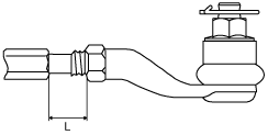
4. Rotate the tie rod and adjust the steering angle.
5. Rotate the tie rod and adjust so that the length L shown in the figure is within the specification.
acxuuw00000348
|
6. Tighten the locknut of the tie-rod end.
7. Correct the rack boot twists.
8. Install and fix the rack boot clamp.
9. After adjusting the steering angle, always inspect and adjust the total toe-in.
Camber and Caster Adjustment
1. Remove the windshield wiper arm (LH). (See WINDSHIELD WIPER ARM AND BLADE REMOVAL/INSTALLATION.)
2. Partially peel back the cowl grille. (See COWL GRILLE REMOVAL/INSTALLATION.)
3. Jack up the front of the vehicle and support it on safety stands.
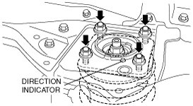
4. Remove the mounting rubber nuts.
acxuuw00002203
|
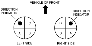
5. Push the shock absorber and coil spring component downward, and turn the direction indicator to the desired position.
acxuuw00001947
|
Adjustment value from original position
|
Direction indicator position |
Camber angle |
Caster angle |
|---|---|---|
|
A
|
0°
|
−0°22′
|
|
B
|
+0°22′
|
−0°22′
|
|
C
|
+0°22′
|
0°
|
6. Install the shock absorber and coil spring, then tighten the mounting rubber nuts to the specified torque.
7. Install the cowl grille. (See COWL GRILLE REMOVAL/INSTALLATION.)
8. Install the windshield wiper arm (LH). (See WINDSHIELD WIPER ARM AND BLADE REMOVAL/INSTALLATION.)
Total Toe-in Adjustment
1. Jack up the front of the vehicle and support it on safety stands.
2. Loosen the locknut of the tie-rod end.
3. Remove the rack boot clamp.
4. Adjust the total toe-in by rotating each tie rod (left and right) in the opposite directions by the same amount respectively.
5. Tighten the locknut of the tie-rod end.
6. Verify that the rack boot does not have any twisting and install the rack boot clamp.