|
ac9wzw00001055
REAR DIFFERENTIAL ASSEMBLY
id031400800600
1. Assemble in the order indicated in the table.
ac9wzw00001055
|
|
1
|
Gear case
|
|
2
|
Side bearing inner race
|
|
3
|
Thrust washer
(See Thrust washer Assembly Note.)
|
|
4
|
Side gear
|
|
5
|
Pinion gear
|
|
6
|
Pinion shaft
|
|
7
|
Knock pin
|
|
8
|
Ring gear
(See Ring Gear Assembly Note.)
|
|
9
|
Differential carrier
|
|
10
|
Bearing outer race
|
|
11
|
Spacer
|
|
12
|
Bearing inner race (rear bearing)
|
|
13
|
Bearing inner race (front bearing)
|
|
14
|
Collapsible spacer
|
|
15
|
Drive pinion
|
|
16
|
Locknut
(See Locknut Assembly Note.)
|
|
17
|
Washer
|
|
18
|
Adjusting shim (LH)
(See Adjusting Shim Assembly Note.)
|
|
19
|
Spacer
|
|
20
|
Side bearing outer race
|
|
21
|
Rear differential component
|
|
22
|
Adjusting shim (RH)
(See Adjusting Shim Assembly Note.)
|
|
23
|
Bearing cap
(See Bearing Cap Assembly Note.)
|
|
24
|
Rear cover
(See Rear Cover Assembly Note.)
|
|
25
|
Differential oil temperature sensor
|
|
26
|
Oil seal
(See Oil Seal Assembly Note.)
|
Side Bearing Inner Race Assembly Note
1. Press the side bearing inner races into the gear case using the SSTs.
ac9wzw00000823
|
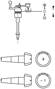
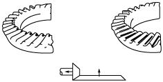
Thrust washer Assembly Note
1. Assemble the side gears, thrust washers and pinion gears to the gear case, then assemble the knock pin.
2. After assembling the knock pin, make a crimp so that the pin will not come out of the gear case.
3. Set a dial gauge to the pinion gear as indicated in the figure.
ac9wzw00000072
|
4. Secure one of the side gears.
5. Move the pinion gear and measure the backlash at the end of the pinion gear.
Thrust washer thickness
|
Identification mark |
Thickness |
|---|---|
|
0
|
2.0 mm {0.079 in}
|
|
1
|
2.1 mm {0.083 in}
|
|
2
|
2.2 mm {0.086 in}
|
|
05
|
2.05 mm {0.081 in}
|
|
15
|
2.15 mm {0.084 in}
|
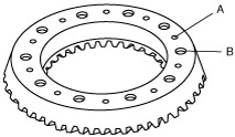
Ring Gear Assembly Note
1. Apply a small amount of thread-locking compound to each of points A on the back of the ring gear, and bolt thread areas B (around the entire ring).
ac9wzw00000073
|
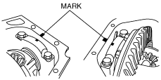
2. Align the marks placed on the ring gear case at the time of disassembly and tighten the bolts in diagonal order.
ac9wzw00001146
|
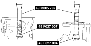
Bearing Outer Race Assembly Note
1. Press in the bearing outer race using the SSTs and a press.
ac9wzw00000075
|
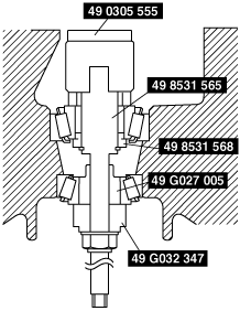
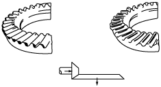
Spacer, Bearing Inner Race Assembly Note
Pinion height adjustment
1. Assemble the spacer, the bearing inner race (rear bearing), and the SST O-ring to the SST (49 8531 565) as shown in the figure.
ac9wzw00000076
|
2. Insert the set assembled in Step 1 to the differential gear from the rear.
3. Assemble the bearing inner race (front bearing), SST (49 G027 005), companion flange, washer, and locknut from the front of the differential gear.
4. Tighten the locknut to the extent that the SST (49 8531 565) can be turned by hand.
5. Place the SST (49 0305 555) on top of the SST (49 8531 565).
6. Place the SST on the surface plate and set the dial indicator to zero.
ac9wzw00000824
|
7. Set the SST as shown in the figure.
ac9wzw00000825
|
8. Place the measuring probe of the dial indicator so that it contacts the place where the side bearing is installed in the carrier. Then measure the left and right side of the lower position.
9. Add the two (left and right) values obtained by the measurements taken in Step 8 and then divide the total by 2. From this result, subtract the result obtained by dividing the number inscribed on the end surface of the drive pinion by 100. (If there is no figure inscribed, use 0.) This is the pinion height adjustment value.
ac9wzw00000079
|
Spacer thickness
|
Identification mark |
Thickness (mm {in}) |
Identification mark |
Thickness (mm {in}) |
|---|---|---|---|
|
08
|
3.08 {0.1213}
|
29
|
3.29 {0.1295}
|
|
09
|
3.095 {0.1219}
|
30
|
3.305 {0.1301}
|
|
11
|
3.11 {0.1224}
|
32
|
3.32 {0.1307}
|
|
12
|
3.125 {0.1230}
|
33
|
3.335 {0.1313}
|
|
14
|
3.14 {0.1236}
|
35
|
3.35 {0.1319}
|
|
15
|
3.155 {0.1242}
|
36
|
3.365 {0.1325}
|
|
17
|
3.17 {0.1248}
|
38
|
3.38 {0.1331}
|
|
18
|
3.185 {0.1254}
|
39
|
3.395 {0.1337}
|
|
20
|
3.20 {0.1260}
|
41
|
3.41 {0.1343}
|
|
21
|
3.215 {0.1266}
|
42
|
3.425 {0.1348}
|
|
23
|
3.23 {0.1272}
|
44
|
3.44 {0.1354}
|
|
24
|
3.245 {0.1278}
|
45
|
3.455 {0.1360}
|
|
26
|
3.26 {0.1283}
|
47
|
3.47 {0.1366}
|
|
27
|
3.275 {0.1289}
|
—
|
—
|
10. Assemble the spacer selected for the pinion height adjustment to the drive pinion.
11. Press the bearing inner race (rear bearing) into the drive pinion using the SSTs and a press.
ac9wzw00000080
|
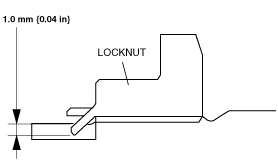
Locknut Assembly Note
Drive pinion preload adjustment
1. Apply differential oil to a new locknut.
2. Assemble a new collapsible spacer, bearing inner race (front bearing), spacer and locknut to the drive pinion, and temporarily tighten the locknut.
3. Turn the serrated part of the drive pinion by hand to seat the bearing.
4. Tighten the locknut temporarily tightened in Step 1 from the lower limit of the specified tightening torque using the SSTs, and make this the specified preload.
ac9wzw00000081
|
5. Crimp the locknut using a chisel and hammer.
ac9wzw00000082
|
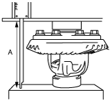
Adjusting Shim Assembly Note
1. Assemble the differential carrier to the SSTs.
2. Assemble the spacer to the differential carrier.
3. Stack the side bearing outer race and gear case component on the surface plate as indicated in the figure, and measure the height using a caliper and a ruler. This is value A.
ac9wzw00000083
|
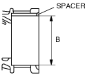
4. Measure the width of the installed differential in the differential carrier with the spacer installed. This is value B.
ac9wzw00000084
|
5. The combined thickness of the left and right adjusting shims is obtained by the following formula.
C1= B – A + 0.15 mm {0.006 in}
6. If the combined thickness of the previously installed adjusting shims is between C1 and C2, use the shims as they are.
7. If the combined thickness of the previously installed adjusting shims is not between C1 and C2, or if the adjusting shims have to be replaced, select two appropriate adjusting shims from the table below.
Adjusting shim thickness
|
Identification mark |
Thickness (mm {in}) |
Identification mark |
Thickness (mm {in}) |
|---|---|---|---|
|
350
|
3.50 {0.137}
|
410
|
4.10 {0.161}
|
|
355
|
3.55 {0.139}
|
415
|
4.15 {0.163}
|
|
360
|
3.60 {0.141}
|
420
|
4.20 {0.165}
|
|
365
|
3.65 {0.143}
|
425
|
4.25 {0.167}
|
|
370
|
3.70 {0.145}
|
430
|
4.30 {0.169}
|
|
375
|
3.75 {0.147}
|
435
|
4.35 {0.171}
|
|
380
|
3.80 {0.149}
|
440
|
4.40 {0.173}
|
|
385
|
3.85 {0.151}
|
445
|
4.45 {0.175}
|
|
390
|
3.90 {0.153}
|
450
|
4.50 {0.177}
|
|
395
|
3.95 {0.155}
|
455
|
4.55 {0.179}
|
|
400
|
4.00 {0.157}
|
460
|
4.60 {0.181}
|
|
405
|
4.05 {0.159}
|
—
|
—
|
8. Assemble the selected adjusting shims to the differential carrier ring gear side, and the spacer to the opposite side.
9. Assemble the differential and bearing outer race to the differential carrier.
10. Tap the selected adjusting shim between the spacer and the bearing race with a plastic hammer as shown in the figure.
ac9wzw00000085
|
11. Align the bearing cap alignment marks to assemble the bearing cap, and temporarily tighten the bolts.
12. Place the dial indicator so that the measuring probe contacts the top surface of one of the ring gear teeth perpendicularly.
13. Secure the drive pinion and measure the backlash from when the ring gear moved.
14. If the backlash is not within the specification, adjust the gear case component by moving it in the axial direction.
Bearing Cap Assembly Note
1. Align the bearing cap alignment marks to assemble the bearing cap.
2. Inspect the drive pinion and ring gear teeth contact points.
ac9wzw00000086
|
ac9wzw00000087
|
ac9wzw00000088
|
ac9wzw00000089
|
Rear Cover Assembly Note
1. Clean the alignment surface of the carrier and rear cover, and apply a thin coat of sealant.
2. Install the rear cover.
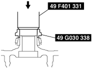
Oil Seal Assembly Note
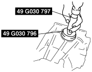
1. Apply differential oil to the new oil seal lip.
2. Assemble the oil seal using the SSTs.
ac9wzw00001147
|