 |
ac9wzw00001416
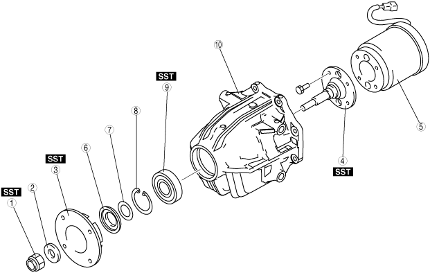
COUPLING COMPONENT DISASSEMBLY
id031800805400
1. Disassemble in the order indicated in the table.
ac9wzw00001416
|
|
1
|
Locknut
(See Locknut Disassembly Note.)
|
|
2
|
Washer
|
|
3
|
Companion flange
|
|
4
|
Output shaft
|
|
5
|
Coupling component
|
|
6
|
Oil seal
|
|
7
|
Shim
|
|
8
|
Snap ring
|
|
9
|
Bearing
(See Bearing Disassembly Note.)
|
|
10
|
Coupling case
|
Locknut Disassembly Note
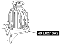
1. Assemble the SSTs to the engine stand.
ac9uuw00001831
|
2. Install the coupling unit to the SSTs as shown.
ac9uuw00001832
|
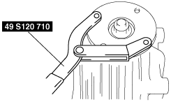
3. Secure the companion flange using the SST, and remove the locknut.
ac9uuw00001833
|
Companion Flange Disassembly Note
1. Remove the companion flange using the SST.
ac9uuw00001834
|
Output Shaft Disassembly Note
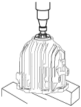
1. Remove the coupling unit from the SST.
2. Install the coupling unit to the press as shown, and remove the output shaft together with the coupling unit.
ac9uuw00001835
|
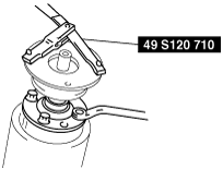
3. Install the companion flange to the output shaft.
4. Secure the companion flange using the SST, and remove the bolts.
ac9uuw00001836
|
5. Remove the output shaft.
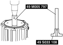
Bearing Disassembly Note
1. Remove the bearing using the SSTs and a press.
ac9wzw00001182
|