ac9uun00000777
|
ON-BOARD DIAGNOSTIC SYSTEM MALFUNCTION DETECTION FUNCTION [AY6A-EL, AY6AX-EL]
id0502k1280100
Special Features
DTC 7-Digit Code Definition
ac9uun00000777
|
DTC Table
|
DTC No. |
MIL |
AT warning light |
Definition |
Fail-safe |
Drive cycle (MIL illuminates) |
Self test type*1 |
Memory function |
|---|---|---|---|---|---|---|---|
|
P0220:00
|
Illuminate
|
Illuminate
|
Accelerator pedal position circuit
|
X
|
1
|
C
|
X
|
|
P0601:00
|
Illuminate
|
Illuminate
|
Flash ROM error
|
X
|
1
|
C
|
X
|
|
P0603:00
|
Illuminate
|
Illuminate
|
EEPROM error
|
X
|
1
|
C
|
X
|
|
P0604:00
|
Illuminate
|
Illuminate
|
RAM error
|
X
|
1
|
C
|
X
|
|
P0702:00
|
Illuminate
|
Illuminate
|
Linear solenoid driver electrical
|
X
|
1
|
C
|
X
|
|
P0706:00
|
Illuminate
|
Illuminate
|
TR switch circuit range/performance
|
X
|
1
|
C
|
X
|
|
P0707:00
|
Illuminate
|
Illuminate
|
TR switch circuit low
|
X
|
1
|
C
|
X
|
|
P0708:00
|
Illuminate
|
Illuminate
|
TR switch circuit high
|
X
|
1
|
C
|
X
|
|
P0711:00
|
Illuminate
|
Illuminate
|
TFT sensor circuit range/performance
|
X
|
1
|
C
|
X
|
|
P0712:00
|
Illuminate
|
Illuminate
|
TFT sensor circuit low
|
X
|
1
|
C
|
X
|
|
P0713:00
|
Illuminate
|
Illuminate
|
TFT sensor circuit high
|
X
|
1
|
C
|
X
|
|
P0715:00
|
Illuminate
|
Illuminate
|
Input/turbine speed sensor circuit
|
X
|
1
|
C
|
X
|
|
P0717:00
|
Illuminate
|
Illuminate
|
Input/turbine speed sensor circuit no signal
|
X
|
1
|
C
|
X
|
|
P0720:00
|
Illuminate
|
Illuminate
|
VSS circuit
|
X
|
1
|
C
|
X
|
|
P0722:00
|
Illuminate
|
Illuminate
|
VSS circuit no signal
|
X
|
1
|
C
|
X
|
|
P0727:00
|
Illuminate
|
Illuminate
|
Engine speed input circuit no signal
|
X
|
1
|
C
|
X
|
|
P0729:00
|
Illuminate
|
Illuminate
|
Gear 6 incorrect ratio
|
X
|
2
|
C
|
X
|
|
P072D:00
|
-
|
Illuminate
|
Incorrect gear ratio (1GR with engine brake stuck 2GR/3GR)
|
X
|
-
|
C
|
X
|
|
P0730:00
|
Illuminate
|
Illuminate
|
Incorrect gear ratio (1GR with engine brake stuck 4GR)
|
X
|
2
|
C
|
X
|
|
P0731:00
|
Illuminate
|
Illuminate
|
Gear 1 incorrect ratio
|
X
|
2
|
C
|
X
|
|
P0732:00
|
Illuminate
|
Illuminate
|
Gear 2 incorrect ratio
|
X
|
2
|
C
|
X
|
|
P0733:00
|
Illuminate
|
Illuminate
|
Gear 3 incorrect ratio
|
X
|
2
|
C
|
X
|
|
P0734:00
|
Illuminate
|
Illuminate
|
Gear 4 incorrect ratio
|
X
|
2
|
C
|
X
|
|
P0735:00
|
Illuminate
|
Illuminate
|
Gear 5 incorrect ratio
|
X
|
2
|
C
|
X
|
|
P073F:00
|
-
|
Illuminate
|
Incorrect Gear Ratio (1GR with engine brake)
|
X
|
-
|
C
|
X
|
|
P074A:00
|
-
|
Illuminate
|
Gear 2 stuck
|
X
|
-
|
C
|
X
|
|
P074B:00
|
-
|
Illuminate
|
Gear 3 stuck
|
X
|
-
|
C
|
X
|
|
P074C:00
|
-
|
Illuminate
|
Gear 4 stuck
|
X
|
-
|
C
|
X
|
|
P074D:00
|
-
|
Illuminate
|
Gear 5 stuck
|
X
|
-
|
C
|
X
|
|
P074E:00
|
-
|
Illuminate
|
Gear 6 stuck
|
X
|
-
|
C
|
X
|
|
P0762:00
|
Illuminate
|
Illuminate
|
Shift solenoid C stuck on
|
X
|
2
|
C
|
X
|
|
P0766:00
|
Illuminate
|
Illuminate
|
Shift solenoid D performance or stuck off
|
X
|
2
|
C
|
X
|
|
P0771:00
|
Illuminate
|
Illuminate
|
Shift solenoid E performance or stuck off
|
X
|
2
|
C
|
X
|
|
P0817:00
|
-
|
Illuminate
|
Starter lock output signal circuit
|
-
|
-
|
C
|
X
|
|
P0819:00
|
-
|
Illuminate
|
Up and down switch to transaxle range correlation
|
X
|
-
|
C
|
X
|
|
P0867:00
|
-
|
Illuminate
|
ATF pressure
|
-
|
-
|
C
|
X
|
|
P0882:00
|
Illuminate
|
Illuminate
|
TCM B+ low
|
X
|
1
|
C
|
X
|
|
P0883:00
|
Illuminate
|
Illuminate
|
TCM B+ high
|
X
|
1
|
C
|
X
|
|
P0942:00
|
Illuminate
|
Illuminate
|
Hydraulic pressure unit (at D position)
|
X
|
2
|
C
|
X
|
|
P0961:00
|
Illuminate
|
Illuminate
|
Line pressure control solenoid circuit range/performance
|
X
|
1
|
C
|
X
|
|
P0962:00
|
Illuminate
|
Illuminate
|
Line pressure control solenoid circuit low
|
X
|
1
|
C
|
X
|
|
P0963:00
|
Illuminate
|
Illuminate
|
Line pressure control solenoid circuit high
|
X
|
1
|
C
|
X
|
|
P0973:00
|
Illuminate
|
Illuminate
|
Shift solenoid A circuit low
|
X
|
1
|
C
|
X
|
|
P0974:00
|
Illuminate
|
Illuminate
|
Shift solenoid A circuit high
|
X
|
1
|
C
|
X
|
|
P0976:00
|
Illuminate
|
Illuminate
|
Shift solenoid B circuit low
|
X
|
1
|
C
|
X
|
|
P0977:00
|
Illuminate
|
Illuminate
|
Shift solenoid B circuit high
|
X
|
1
|
C
|
X
|
|
P0978:00
|
Illuminate
|
Illuminate
|
Shift solenoid C circuit range/performance
|
X
|
1
|
C
|
X
|
|
P0979:00
|
Illuminate
|
Illuminate
|
Shift solenoid C circuit low
|
X
|
1
|
C
|
X
|
|
P0980:00
|
Illuminate
|
Illuminate
|
Shift solenoid C circuit high
|
X
|
1
|
C
|
X
|
|
P0981:00
|
Illuminate
|
Illuminate
|
Shift solenoid D circuit range/performance
|
X
|
1
|
C
|
X
|
|
P0982:00
|
Illuminate
|
Illuminate
|
Shift solenoid D circuit low
|
X
|
1
|
C
|
X
|
|
P0983:00
|
Illuminate
|
Illuminate
|
Shift solenoid D circuit high
|
X
|
1
|
C
|
X
|
|
P0984:00
|
Illuminate
|
Illuminate
|
Shift solenoid E circuit range/performance
|
X
|
1
|
C
|
X
|
|
P0985:00
|
Illuminate
|
Illuminate
|
Shift solenoid E circuit low
|
X
|
1
|
C
|
X
|
|
P0986:00
|
Illuminate
|
Illuminate
|
Shift solenoid E circuit high
|
X
|
1
|
C
|
X
|
|
P0997:00
|
Illuminate
|
Illuminate
|
Shift solenoid F circuit range/performance
|
X
|
1
|
C
|
X
|
|
P0998:00
|
Illuminate
|
Illuminate
|
Shift solenoid F circuit low
|
X
|
1
|
C
|
X
|
|
P0999:00
|
Illuminate
|
Illuminate
|
Shift solenoid F circuit high
|
X
|
1
|
C
|
X
|
|
P1700:00
|
-
|
Illuminate
|
Hydraulic pressure unit (at R position)
|
X
|
-
|
C
|
X
|
|
P1719:00
|
-
|
-
|
Engine torque signal error (inaccurate signal)
|
X
|
-
|
C
|
X
|
|
P1738:00
|
-
|
Illuminate
|
Shift control solenoid component malfunction
|
X
|
-
|
C
|
X
|
|
P1783:00
|
-
|
-
|
ATF high oil temperature malfunction
|
X
|
-
|
C
|
X
|
|
P1919:00
|
-
|
-
|
Engine coolant temperature signal error
|
X
|
-
|
C
|
X
|
|
P2544:00
|
Illuminate
|
Illuminate
|
Engine torque signal error (invalid signal)
|
X
|
1
|
C
|
X
|
|
P2708:00
|
Illuminate
|
Illuminate
|
Shift solenoid F stuck on
|
X
|
2
|
C
|
X
|
|
P2757:00
|
Illuminate
|
Illuminate
|
TCC control solenoid circuit performance or stuck off
|
X
|
2
|
C
|
X
|
|
P2762:00
|
Illuminate
|
Illuminate
|
TCC control solenoid range/performance
|
X
|
1
|
C
|
X
|
|
P2763:00
|
Illuminate
|
Illuminate
|
TCC control solenoid circuit high
|
X
|
1
|
C
|
X
|
|
P2764:00
|
Illuminate
|
Illuminate
|
TCC control solenoid circuit low
|
X
|
1
|
C
|
X
|
|
P2806:00
|
-
|
Illuminate
|
Neutral position learning (Not performed yet)
|
X
|
-
|
C
|
X
|
|
U0073:00
|
Illuminate
|
Illuminate
|
Control module communication bus off
|
X
|
1
|
C
|
X
|
|
U0100:00
|
Illuminate
|
Illuminate
|
Lost communication with PCM
|
X
|
1
|
C
|
X
|
|
U0121:00
|
-
|
Illuminate
|
Lost communication with DSC/RSC HU/CM
|
X
|
-
|
C
|
X
|
|
U0155:00
|
-
|
-
|
Lost communication with instrument cluster
|
X
|
-
|
C
|
X
|
|
U0415:00
|
-
|
-
|
Invalid data received from DSC/RSC HU/CM
|
X
|
-
|
C
|
X
|
DTC Separate Detection Condition
|
DTC No. |
Definition |
Detection condition |
|---|---|---|
|
P0220:00
|
Accelerator pedal position circuit
|
• Conditions: TCM communication normal
• Circumstances: Accelerator pedal position signal abnormality detected
• Time period: Determined after 1 times
|
|
P0601:00
|
Flash ROM error
|
• Conditions: Ignition switch ON
• Circumstances: Internal abnormality detected by flash ROM
• Time period: Determined after 1 time
|
|
P0603:00
|
EEPROM error
|
• Conditions: Ignition switch ON
• Circumstances: Different values detected for EEPROM and RAM
• Time period: Determined after 1 time
|
|
P0604:00
|
RAM error
|
• Conditions: Ignition switch ON
• Circumstances: RAM reading or writing error detected
• Time period: Determined after 1 time
|
|
P0702:00
|
Linear solenoid driver electrical
|
• Conditions: TCM communication normal
• Circumstances: Inappropriate current for solenoid current command value detected
• Time period: Determined after 5 consecutive times lasting 0.08 or more seconds
|
|
P0706:00
|
TR switch circuit range/performance
|
• Conditions: Battery voltage is normal
• Circumstances: TR switch stuck detected
• Time period: Determined after 2 consecutive times lasting 0.1 or more seconds
|
|
P0707:00
|
TR switch circuit low
|
• Conditions: Battery voltage is normal
• Circumstances: TR switch voltage below 0.127V detected
• Time period: Determined after 2 consecutive times lasting 0.1 or more seconds
|
|
P0708:00
|
TR switch circuit high
|
• Conditions: Battery voltage is normal
• Circumstances: TR switch voltage above 4.84V detected
• Time period: Determined after 2 consecutive times lasting 0.1 or more seconds
|
|
P0711:00
|
TFT sensor circuit range/performance
|
• Stuck low temperature
• Stuck high temperature
|
|
P0712:00
|
TFT sensor circuit low
|
• Conditions: TCM communication normal
• Circumstances: ATF temperature of 200 °C {392 °F} or above detected
• Time period: Determined after 6 times lasting 10 or more seconds
|
|
P0713:00
|
TFT sensor circuit high
|
• Conditions: Engine warmed-up and running, TCM communication normal
• Circumstances: ATF temperature of below -55 °C {-67 °F} detected
• Time period: Determined after 12 times lasting 1 or more seconds
|
|
P0715:00
|
Input/turbine speed sensor circuit
|
• Conditions: TCM communication normal
• Circumstances: Normal Input/turbine speed sensor signal not input
• Time period: Determined after 10 times lasting 0.1 or more seconds
|
|
P0717:00
|
Input/turbine speed sensor circuit no signal
|
• Conditions: Engine running, TCM communication normal, driving in D position, vehicle speed over 20 km/h {12 mph}
• Circumstances: Input/turbine speed sensor signal not input with VSS 24 pulse
• Time period: Determined after 500 consecutive times
|
|
P0720:00
|
VSS circuit
|
• Conditions: TCM communication normal
• Circumstances: Normal VSS signal not input
• Time period: Determined after 10 times lasting 0.1 or more seconds
|
|
P0722:00
|
VSS circuit no signal
|
• Conditions: Engine running, TCM communication normal, driving in D position, vehicle speed over 20 km/h {12 mph}
• Circumstances: VSS signal not input with input/turbine speed sensor 16 pulse
• Time period: Determined after 500 consecutive times
|
|
P0727:00
|
Engine speed input circuit no signal
|
• Conditions: TCM communication normal
• Circumstances: Engine speed signal abnormality detected
• Time period: Determined after 1 times
|
|
P0729:00
|
Gear 6 incorrect ratio
|
• Conditions: ATF temperature 20 °C {68 °F} or more, speed sensor normal, TCM communication normal, accelerator pedal position 10% or more, driving in D position, 6GR
• Circumstances: Not in 6GR ratio detected
• Time period: Determined after 12 times lasting 1 or more seconds
|
|
P072D:00
|
Incorrect gear ratio (1GR with engine brake stuck 2GR/3GR)
|
• Conditions: ATF temperature 20 °C {68 °F} or more, speed sensor normal, TCM communication normal, accelerator pedal position 10% or more, driving in manual mode, 1GR
• Circumstances: Not 1st engine brake detected
• Time period: Determined after 5 times lasting 0.5 or more seconds
|
|
P0730:00
|
Incorrect gear ratio (1GR with engine brake stuck 4GR)
|
• Conditions: ATF temperature 20 °C {68 °F} or more, speed sensor normal, TCM communication normal, accelerator pedal position 10% or more, driving in manual mode, 1GR
• Circumstances: Not 1st engine brake detected
• Time period: Determined after 12 times lasting 1 or more seconds
|
|
P0731:00
|
Gear 1 incorrect ratio
|
• Conditions: ATF temperature 20 °C {68 °F} or more, speed sensor normal, TCM communication normal, accelerator pedal position 10% or more, driving in D position, 1GR
• Circumstances: Not in 1GR ratio detected
• Time period: Determined after 5 times lasting 0.5 or more seconds
|
|
P0732:00
|
Gear 2 incorrect ratio
|
• Conditions: ATF temperature 20 °C {68 °F} or more, speed sensor normal, TCM communication normal, accelerator pedal position 10% or more, driving in D position, 2GR
• Circumstances: Not in 2GR ratio detected
• Time period: Determined after 12 times lasting 1 or more seconds
|
|
P0733:00
|
Gear 3 incorrect ratio
|
• Conditions: ATF temperature 20 °C {68 °F} or more, speed sensor normal, TCM communication normal, accelerator pedal position 10% or more, driving in D position, 3GR
• Circumstances: Not in 3GR ratio detected
• Time period: Determined after 12 times lasting 1 or more seconds
|
|
P0734:00
|
Gear 4 incorrect ratio
|
• Conditions: ATF temperature 20 °C {68 °F} or more, speed sensor normal, TCM communication normal, accelerator pedal position 10% or more, driving in D position, 4GR
• Circumstances: Not in 4GR ratio detected
• Time period: Determined after 12 times lasting 1 or more seconds
|
|
P0735:00
|
Gear 5 incorrect ratio
|
• Conditions: ATF temperature 20 °C {68 °F} or more, speed sensor normal, TCM communication normal, accelerator pedal position 10% or more, driving in D position, 5GR
• Circumstances: Not in 5GR ratio detected
• Time period: Determined after 12 times lasting 1 or more seconds
|
|
P073F:00
|
Incorrect Gear Ratio (1GR with engine brake)
|
• Conditions: ATF temperature 20 °C {68 °F} or more, speed sensor normal, TCM communication normal, accelerator pedal position 10% or more, driving in manual mode, 1GR
• Circumstances: Not 1st engine brake detected
• Time period: Determined after 12 times lasting 1 or more seconds
|
|
P074A:00
|
Gear 2 stuck
|
• Conditions: ATF temperature 20 °C {68 °F} or more, speed sensor normal, TCM communication normal, accelerator pedal position 10% or more, driving in D position, 2GR
• Circumstances: Not in 2GR ratio detected
• Time period: Determined after 5 times lasting 1 or more seconds
|
|
P074B:00
|
Gear 3 stuck
|
• Conditions: ATF temperature 20 °C {68 °F} or more, speed sensor normal, TCM communication normal, accelerator pedal position 10% or more, driving in D position, 3GR
• Circumstances: Not in 3GR ratio detected
• Time period: Determined after 5 times lasting 1 or more seconds
|
|
P074C:00
|
Gear 4 stuck
|
• Conditions: ATF temperature 20 °C {68 °F} or more, speed sensor normal, TCM communication normal, accelerator pedal position 10% or more, driving in D position, 4GR
• Circumstances: Not in 4GR ratio detected
• Time period: Determined after 5 times lasting 1 or more seconds
|
|
P074D:00
|
Gear 5 stuck
|
• Conditions: ATF temperature 20 °C {68 °F} or more, speed sensor normal, TCM communication normal, accelerator pedal position 10% or more, driving in D position, 5GR
• Circumstances: Not in 5GR ratio detected
• Time period: Determined after 5 times lasting 1 or more seconds
|
|
P074E:00
|
Gear 6 stuck
|
• Conditions: ATF temperature 20 °C {68 °F} or more, speed sensor normal, TCM communication normal, accelerator pedal position 10% or more, driving in D position, 6GR
• Circumstances: Not in 6GR ratio detected
• Time period: Determined after 5 times lasting 1 or more seconds
|
|
P0762:00
|
Shift solenoid C stuck on
|
• Conditions: ATF temperature -20 °C {68 °F} or more, TCM communication normal, driving in D position, output VSS rotation 300 rpm or more (wheel not spinning)
• Circumstances: Abnormal shifting detected
• Time period: Determined after 5 times
|
|
P0766:00
|
Shift solenoid D performance or stuck off
|
• Conditions: ATF temperature -20 °C {68 °F} or more, TCM communication normal, driving in D position, output VSS rotation 300 rpm or more (wheel not spinning)
• Circumstances: Abnormal shifting detected
• Time period: Determined after 5 times
|
|
P0771:00
|
Shift solenoid E performance or stuck off
|
• Conditions: ATF temperature -20 °C {68 °F} or more, TCM communication normal, driving in D position, output VSS rotation 300 rpm or more (wheel not spinning)
• Circumstances: Abnormal shifting detected
• Time period: Determined after 5 times
|
|
P0817:00
|
Starter lock output signal circuit
|
• B+ short
• GND short / open
|
|
P0819:00
|
Up and down switch to transaxle range correlation
|
• Conditions: Engine running and TCM communication normal
• Circumstances: M position (5V) signal is detected with the shift lever in a position except D position, or M position (0V) signal is detected when the shift lever is in the UP or DOWN position
• Time period: Determined after 1 times lasting 10 or more seconds
|
|
P0867:00
|
ATF pressure
|
• Conditions: In D position, VSS rotation 500rpm or below, ATF temperature 0 °C or more, Not shifting, 1GR, 2GR, 3GR or 4GR
• Circumstances: Difference between engine speed and Input/turbine speed sensor rotation below 150rpm, not in 1GR detected, input revolution > output revolution × 1GR ratio + 400rpm
• Time period: Determined C1 and C2 clutch not engaged after 1 times lasting 0.1 or more continuous
|
|
P0882:00
|
TCM B+ low
|
• Conditions: Engine idling and TCM communication normal
• Circumstances: Ignition terminal voltage under 9V detected
• Time period: Determined after 20 times lasting 1 or more seconds
|
|
P0883:00
|
TCM B+ high
|
• Conditions: Engine idling and TCM communication normal
• Circumstances: Ignition terminal voltage 18V or more detected
• Time period: Determined after 5 times lasting 1 or more seconds
|
|
P0942:00
|
Hydraulic pressure unit (at D position)
|
• Conditions: In D position, VSS rotation 500rpm or below
• Circumstances: Difference between engine rotation and Input/turbine speed sensor rotation below 150rpm, not in 1GR detected
• Time period: Determined after 1 times lasting 0.8 or more seconds
|
|
P0961:00
|
Line pressure control solenoid circuit range/performance
|
• Conditions: TCM communication normal
• Circumstances: Inappropriate feedback current for solenoid current command value detected
• Time period: Determined after lasting 2 or more seconds
|
|
P0962:00
|
Line pressure control solenoid circuit low
|
• Conditions: TCM communication normal
• Circumstances: line pressure control solenoid system disconnection or short circuit to GND detected
• Time period: Determined after 5 consecutive times lasting 0.1 or more seconds
|
|
P0963:00
|
Line pressure control solenoid circuit high
|
• Conditions: TCM communication normal
• Circumstances: Short circuit between line pressure control solenoid and power systems detected
• Time period: Determined after 5 consecutive times lasting 0.1 or more seconds
|
|
P0973:00
|
Shift solenoid A circuit low
|
• Conditions: TCM communication normal
• Circumstances: Short circuit between shift solenoid A and GND systems detected
• Time period: Determined after 5 times lasting 0.1 or more seconds
|
|
P0974:00
|
Shift solenoid A circuit high
|
• Conditions: TCM communication normal
• Circumstances: Shift solenoid A system disconnection or short circuit detected
• Time period: Determined after 5 times lasting 0.1 or more seconds
|
|
P0976:00
|
Shift solenoid B circuit low
|
• Conditions: TCM communication normal
• Circumstances: Short circuit between shift solenoid B and GND systems detected
• Time period: Determined after 5 times lasting 0.1 or more seconds
|
|
P0977:00
|
Shift solenoid B circuit high
|
• Conditions: TCM communication normal
• Circumstances: Shift solenoid B system disconnection or short circuit detected
• Time period: Determined after 5 times lasting 0.1 or more seconds
|
|
P0978:00
|
Shift solenoid C circuit range/performance
|
• Conditions: TCM communication normal
• Circumstances: Inappropriate feedback current for solenoid current command value detected
• Time period: Determined after lasting 2 or more seconds
|
|
P0979:00
|
Shift solenoid C circuit low
|
• Conditions: TCM communication normal
• Circumstances: Shift solenoid C system disconnection or short circuit to GND detected
• Time period: Determined after 5 consecutive times lasting 0.1 or more seconds
|
|
P0980:00
|
Shift solenoid C circuit high
|
• Conditions: TCM communication normal
• Circumstances: Short circuit between shift solenoid C and power systems detected
• Time period: Determined after 5 consecutive times lasting 0.1 or more seconds
|
|
P0981:00
|
Shift solenoid D circuit range/performance
|
• Conditions: TCM communication normal
• Circumstances: Inappropriate feedback current for solenoid current command value detected
• Time period: Determined after lasting 2 or more seconds
|
|
P0982:00
|
Shift solenoid D circuit low
|
• Conditions: TCM communication normal
• Circumstances: Shift solenoid D system disconnection or short circuit to GND detected
• Time period: Determined after 5 consecutive times lasting 0.1 or more seconds
|
|
P0983:00
|
Shift solenoid D circuit high
|
• Conditions: TCM communication normal
• Circumstances: Short circuit between shift solenoid D and power systems detected
• Time period: Determined after 5 consecutive times lasting 0.1 or more seconds
|
|
P0984:00
|
Shift solenoid E circuit range/performance
|
• Conditions: TCM communication normal
• Circumstances: Inappropriate feedback current for solenoid current command value detected
• Time period: Determined after lasting 2 or more seconds
|
|
P0985:00
|
Shift solenoid E circuit low
|
• Conditions: TCM communication normal
• Circumstances: Shift solenoid E system disconnection or short circuit to GND detected
• Time period: Determined after 5 consecutive times lasting 0.1 or more seconds
|
|
P0986:00
|
Shift solenoid E circuit high
|
• Conditions: TCM communication normal
• Circumstances: Short circuit between shift solenoid E and power systems detected
• Time period: Determined after 5 consecutive times lasting 0.1 or more seconds
|
|
P0997:00
|
Shift solenoid F circuit range/performance
|
• Conditions: TCM communication normal
• Circumstances: Inappropriate feedback current for solenoid current command value detected
• Time period: Determined after lasting 2 or more seconds
|
|
P0998:00
|
Shift solenoid F circuit low
|
• Conditions: TCM communication normal
• Circumstances: Shift solenoid F system disconnection or short circuit to GND detected
• Time period: Determined after 5 consecutive times lasting 0.1 or more seconds
|
|
P0999:00
|
Shift solenoid F circuit high
|
• Conditions: TCM communication normal
• Circumstances: Short circuit between shift solenoid F and power systems detected
• Time period: Determined after 5 consecutive times lasting 0.1 or more seconds
|
|
P1700:00
|
Hydraulic pressure unit (at R position)
|
• Conditions: In R position, VSS rotation 500rpm or below
• Circumstances: Difference between engine and Input/turbine speed sensor rotations below 150rpm, not in reverse gear detected
• Time period: Determined after 1 times lasting 0.8 or more seconds
|
|
P1719:00
|
Engine torque signal error (inaccurate signal)
|
• Conditions: TCM communication normal
• Circumstances: Engine torque signal abnormality detected
• Time period: Determined after 275 times lasting 0.02 seconds
|
|
P1738:00
|
Shift control solenoid component malfunction
|
• Conditions: ATF temperature -20 °C {68 °F} or more, TCM communication normal, driving in D position, output VSS rotation 300 rpm or more (wheel not spinning)
• Circumstances: Abnormal shifting detected
• Time period: Determined after 5 times
|
|
P1783:00
|
ATF high oil temperature malfunction
|
• Conditions: Engine speed < 800 rpm and TCM communication normal
• Circumstances: ATF temperature of 150 °C {302 °F} or above detected
• Time period: Determined after 1 time lasting 12 seconds
|
|
P1919:00
|
Engine coolant temperature signal error
|
• Conditions: TCM communication normal
• Circumstances: Engine coolant temperature signal abnormality detected
• Time period: Determined after 1 times
|
|
P2544:00
|
Engine torque signal error (invalid signal)
|
• Conditions: TCM communication normal
• Circumstances: Engine torque signal abnormality detected
• Time period: Determined after 1 times
|
|
P2708:00
|
Shift solenoid F stuck on
|
• Conditions: ATF temperature -20 °C {68 °F} or more, TCM communication normal, driving in D position, output VSS rotation 300 rpm or more (wheel not spinning)
• Circumstances: Abnormal shifting detected
• Time period: Determined after 5 times
|
|
P2757:00
|
TCC control solenoid circuit performance or stuck off
|
• Conditions: TCC control solenoid normal, TCC control solenoid ON command, ATF temperature 20 °C {68 °F} or more, TCM communication normal, driving in D position
• Circumstances: Difference between engine and input/turbine speed sensor rotations 100rpm or above detected
• Time period: Determined after 6 times lasting 2 or more seconds
|
|
P2762:00
|
TCC control solenoid range/performance
|
• Conditions: TCM communication normal
• Circumstances: Inappropriate feedback current for solenoid current command value detected
• Time period: Determined after lasting 2 or more seconds
|
|
P2763:00
|
TCC control solenoid circuit high
|
• Conditions: TCM communication normal
• Circumstances: Short circuit between TCC control solenoid and power systems detected
• Time period: Determined after 5 consecutive times lasting 0.1 or more seconds
|
|
P2764:00
|
TCC control solenoid circuit low
|
• Conditions: TCM communication normal
• Circumstances: TCC control solenoid system disconnection or short circuit to GND detected
• Time period: Determined after 5 consecutive times lasting 0.1 or more seconds
|
|
P2806:00
|
Neutral position learning (Not performed yet)
|
• Conditions: Diagnosis tester request “N position adaptation”
• Circumstances: “N position adaptation” not performed
• Time period: Determined after 1 time
|
|
U0073:00
|
Control module communication bus off
|
• Conditions: TCM communication normal
• Circumstances: Bus off abnormality detected
• Time period: Determined with CAN-Mute 400msec (1 time)
|
|
U0100:00
|
Lost communication with PCM
|
• Conditions: TCM communication normal
• Circumstances: PCM communication abnormality detected
• Time period: Determined after 2 consecutive times
|
|
U0121:00
|
Lost communication with DSC/RSC HU/CM
|
• Conditions: TCM communication normal
• Circumstances: DSC/RSC HU/CM communication abnormality detected
• Time period: Determined after 2 consecutive times
|
|
U0155:00
|
Lost communication with instrument cluster
|
• Conditions: TCM communication normal
• Circumstances: Instrument cluster communication abnormality detected
• Time period: Determined after 2 consecutive times
|
|
U0415:00
|
Invalid data received from DSC/RSC HU/CM
|
• Conditions: TCM communication normal
• Circumstances: Each wheel speed abnormality detected
• Time period: Determined after 1 times
|
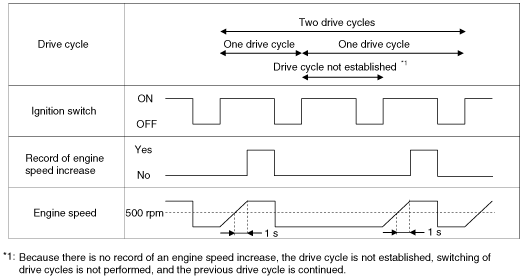
Drive Cycle
Definition
Drive cycle conditions
Record of engine speed increase
Drive cycle switching timing
ac9uun00000846
|
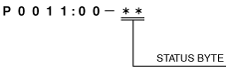
Pending Code
Status Byte for DTC
am5ezn00001608
|
Self-Test Function
CMDTC (Continuous Memory Diagnostic Trouble Code) self-test
Freeze Frame Data
Freeze frame data table
|
Freeze frame data item |
Unit |
Data contents |
Corresponding data monitor items |
|---|---|---|---|
|
LOAD
|
%
|
Charging efficiency
|
LOAD
|
|
ECT
|
°C {°F}
|
Engine coolant temperature
|
ECT
|
|
RPM
|
RPM
|
Engine speed
|
RPM
|
|
VS
|
KPH {MPH}
|
Vehicle speed
|
VSS
|
|
TP
|
%
|
Throttle position sensor
|
THOP
|
|
RUNTM
|
hh:mm:ss
|
Time since engine start
|
—
|
|
VPWR
|
V
|
Power supply voltage
|
VPWR
|
Snap shot data table
|
Snap shot data item |
Unit |
Data contents |
Corresponding data monitor items |
|---|---|---|---|
|
LOAD
|
%
|
Charging efficiency
|
LOAD
|
|
ECT
|
°C {°F}
|
Engine coolant temperature
|
ECT
|
|
RPM
|
RPM
|
Engine speed
|
RPM
|
|
VSS
|
KPH {MPH}
|
Vehicle speed
|
VSS
|
|
TP1
|
%
|
Throttle position sensor
|
THOP
|
|
EG_RUN_TIME
|
hh:mm:ss
|
Time since engine start
|
—
|
|
VPWR
|
V
|
Power supply voltage
|
VPWR
|