MECHANICAL SYSTEM TEST [AW6A-EL, AW6AX-EL]


id051723802100


Mechanical System Test Preparation

1.  Engage the parking brake and use wheel chocks at the front and rear of the wheels.

2.  Inspect the engine coolant level. (See COOLING SYSTEM SERVICE WARNINGS [MZI-3.7].) (See ENGINE COOLANT LEVEL INSPECTION [MZI-3.7].)

3.  Inspect the engine oil level. (See ENGINE OIL LEVEL INSPECTION [MZI-3.7].)

4.  Inspect the ATF level. (See AUTOMATIC TRANSAXLE FLUID (ATF) INSPECTION [AW6A-EL, AW6AX-EL].)

5.  Inspect the idle speed. (See ENGINE TUNE-UP [MZI-3.7].)

6.  Inspect the ignition timing. (See ENGINE TUNE-UP [MZI-3.7].)

7.  Verify that no DTCs recorded. (See DTC TABLE [AW6A-EL, AW6AX-EL].)
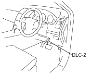

Line Pressure Test

1.  Perform the “Mechanical System Test Preparation”. (SeeMechanical System Test Preparation.)

Warning
•  Removing the test plug when the ATF is hot can be dangerous. Hot ATF can come out of the opening and badly burn you. Before removing the test plug, allow the ATF to cool.
Note
•  Use a suitable oil pressure gauge that corresponds to the line pressure because the maximum scale value differs depending on the oil pressure gauge.

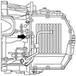
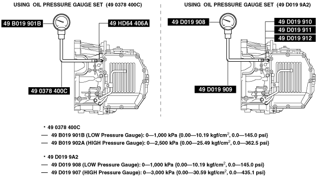
2.  Measure the line pressure while idling in D range.

(1)  Remove the test plug (for the D range line) and the O-ring.
am6xuw00002803
(2)  Connect the SSTs as following:
•  When using the oil pressure gauge set (49 0378 400C), connect the SSTs (49 HD64 406A, 49 0378 400C, 49 B019 901B) to the line pressure inspection port as shown in the figure.
•  When using the oil pressure gauge set (49 D019 9A2), connect the SSTs (49 D019 910, 49 D019 911, 49 D019 912, 49 D019 909, 49 D019 908) to the line pressure inspection port as shown in the figure.
am6xuw00002804
(3)  Start the engine and warm it up until the ATF reaches 60—70 °C {140—158 °F}.
(4)  Shift the selector lever to the D range.
Caution
•  Perform the test at least 3 times and calculate the average.
(5)  Read the line pressure while the engine is idling.

Line pressure specification (while idling)

Test condition

Specification (kPa {kgf/cm2, psi})

Idle
D range
350—410 {3.6—4.1, 51—59}

(6)  Stop the engine.

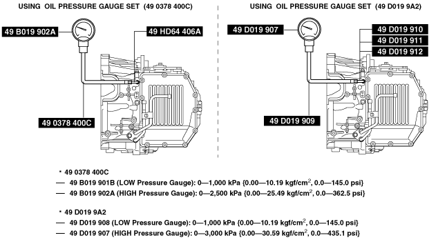
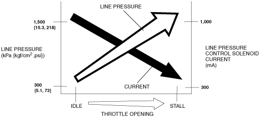
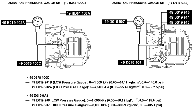
3.  Measure the line pressure while stalling in D range.

(1)  Replace the oil pressure gauge as following:
•  When using the oil pressure gauge set (49 0378 400C), replace the SST (49 B019 901B) with SST (49 B019 902A).
•  When using the oil pressure gauge set (49 D019 9A2), replace the SST (49 D019 908) with SST (49 D019 907).
am6xuw00002807
(2)  Connect the M-MDS to the DLC-2.

L.H.D.

ac9uuw00001943

R.H.D.

ac9wzw00000011
(3)  Monitor the pressure control solenoid current (PID LPS) using the M-MDS data monitor function.
(4)  Start the engine.
(5)  Firmly depress the brake pedal with the left foot.
(6)  Shift the selector lever to the D range.
Caution
•  If the accelerator pedal is pressed for more than 5 s while the brake pedal is pressed, the transmission could be damaged. Therefore, perform Steps (7) and (8) within 5 s.
(7)  Gradually depress the accelerator pedal with the right foot.
(8)  When the engine speed no longer increases, quickly read the line pressure and release the accelerator pedal.
(9)  Verify that the pressure control solenoid current changes as shown in the figure depending on the throttle opening angle.
am6xuw00002810
―  The line pressure standard other than when the engine is idling cannot be determined because the maximum line pressure for this automatic transaxle is controlled by vehicle conditions.
(10)  Shift the selector lever to the N position and idle the engine for 1 min or more to cool the ATF.
(11)  Remove the SSTs.
Warning
•  Removing the SSTs when the ATF is hot can be dangerous. Hot ATF can come out of the opening and badly burn you. Before removing the SSTs, allow the ATF to cool.
(12)  Install the test plug and O-ring in the inspection port.
Tightening torque
5.9—8.8 N·m {61—89 kgf·cm, 53—77 in·lbf}

4.  Measure the line pressure while idling in R position.

(1)  Remove the test plug (for the R position line) and the O-ring.
am6xuw00002803
(2)  Connect the SSTs as following:
•  When using the oil pressure gauge set (49 0378 400C), connect the SSTs (49 HD64 406A, 49 0378 400C, 49 B019 901B) to the line pressure inspection port as shown in the figure.
•  When using the oil pressure gauge set (49 D019 9A2), connect the SSTs (49 D019 910, 49 D019 911, 49 D019 912, 49 D019 909, 49 D019 908) to the line pressure inspection port as shown in the figure.
am6xuw00002805
(3)  Start the engine and warm it up until the ATF reaches 60—70 °C {140—158 °F}.
(4)  Shift the selector lever to the R position.
Caution
•  Perform the test at least 3 times and calculate the average.
(5)  Read the line pressure while the engine is idling.

Line pressure specification (while idling)

Test condition

Specification (kPa {kgf/cm2, psi})

Idle
R position
580—670 {6.0—6.8, 85—97}

(6)  Stop the engine.

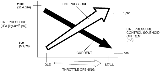
5.  Measure the line pressure while stalling in R position.

(1)  Replace the oil pressure gauge as following:
•  When using the oil pressure gauge set (49 0378 400C), replace the SST (49 B019 901B) with SST (49 B019 902A).
•  When using the oil pressure gauge set (49 D019 9A2), replace the SST (49 D019 908) with SST (49 D019 907).
am6xuw00002806
(2)  Connect the M-MDS to the DLC-2.

L.H.D.

ac9uuw00001943

R.H.D.

ac9wzw00000011
(3)  Monitor the pressure control solenoid current (PID LPS) using the M-MDS data monitor function.
(4)  Start the engine.
(5)  Firmly depress the brake pedal with the left foot.
(6)  Shift the selector lever to the R position.
Caution
•  If the accelerator pedal is pressed for more than 5 s while the brake pedal is pressed, the transmission could be damaged. Therefore, perform Steps (7) and (8) within 5 s.
(7)  Gradually depress the accelerator pedal with the right foot.
(8)  When the engine speed no longer increases, quickly read the line pressure and release the accelerator pedal.
(9)  Verify that the pressure control solenoid current changes as shown in the figure depending on the throttle opening angle.
am6xuw00002811
―  The line pressure standard other than when the engine is idling cannot be determined because the maximum line pressure for this automatic transaxle is controlled by vehicle conditions.
(10)  Shift the selector lever to the N position and idle the engine for 1 min or more to cool the ATF.
(11)  Remove the SSTs.
Warning
•  Removing the SSTs when the ATF is hot can be dangerous. Hot ATF can come out of the opening and badly burn you. Before removing the SSTs, allow the ATF to cool.
(12)  Install the test plug and O-ring in the inspection port.
Tightening torque
5.9—8.8 N·m {61—89 kgf·cm, 53—77 in·lbf}

6.  Perform the “Mechanical System Test Preparation”. (SeeMechanical System Test Preparation.)

Line pressure test evaluation

Condition

Possible cause

Lower than specification in D range and R position
•  Line pressure control solenoid malfunction
•  Primary regulator valve malfunction
•  Oil pump malfunction
•  Oil leaking from D range or R position hydraulic circuit
Constant pressure without fluctuation in hydraulic pressure to throttle in D range and R position
•  Line pressure control solenoid malfunction
•  Control valve body internal malfunction
Current to throttle does not change in D range and R position
•  TCM internal malfunction
•  Connector malfunction
Hydraulic pressure in R position is not higher than D range
•  Primary regulator valve malfunction


Stall Test

1.  Perform the “Mechanical System Test Preparation”. (See Mechanical System Test Preparation.)

2.  Start the engine.

3.  Firmly depress the brake pedal with the left foot.

4.  Shift the selector lever to the D range.

Caution
•  If the accelerator pedal is depressed for more than 5 s while the brake pedal is depressed, the transaxle could be damaged. Therefore, perform Steps 5 and 6 within 5 s.
•  Perform the test at least 3 times and calculate the average.

5.  Gently depress the accelerator pedal with the right foot.

6.  When the engine speed no longer increases, quickly read the engine speed and release the accelerator pedal.

7.  Shift the selector lever to the N position and idle the engine for 1 min or more to cool the ATF.

8.  Perform a stall test of the M range and R position in the same manner as in Steps 3—7.

9.  Turn off the engine.

Stall speed

Test Condition

Specification (rpm)

D
2,637
R
2,555

Evaluation of stall test

Condition

Possible cause

Above specification
In D range
•  Low line pressure (Line pressure control solenoid malfunction, primary regulator valve malfunction)
•  Control valve body component malfunction (shift solenoid C hydraulic pressure system)
•  C1 clutch slipping
•  One-way clutch malfunction
In R position
•  Low line pressure (Line pressure control solenoid malfunction, primary regulator valve malfunction)
•  Control valve body component malfunction (shift solenoid E hydraulic pressure system)
•  C3 clutch malfunction (slipping)
•  B2 brake malfunction (slipping)
In all positions/ranges
•  Low line pressure (Line pressure control solenoid malfunction, primary regulator valve malfunction)
•  Oil pump malfunction
•  Oil strainer clogging
Below specification
•  Engine lack of power
•  Torque converter one-way clutch slipping


Time Lag Test

1.  Perform the “Mechanical System Test Preparation”. (SeeMechanical System Test Preparation.)

2.  Start the engine.

3.  Warm up the engine until the ATF temperature reaches 60—70°C {140—158°F}.

4.  Shift the selector lever from the N position to D range.

5.  Use a stopwatch to measure the time it takes from shifting until shock is felt. Take three measurements for each test and average from the results using the following formula.

Formula
Average time lag = (Time 1 + Time 2 + Time 3) / 3

6.  Perform the test for the following shifts in the same manner as in Step 5.

•  N position → R position

Time lag

Test Condition

Specification (s)

From N position to D range
1.5 or less
From N position to R position
1.5 or less

Evaluation of time lag test

Condition

Possible cause

N→D shift
More than specification
•  Control valve body malfunction (shift solenoid C hydraulic pressure system)
•  C1 clutch slipping
•  One-way clutch malfunction
•  Oil pump malfunction
•  Oil strainer clogging
N→R shift
More than specification
•  Control valve body malfunction (shift solenoid E hydraulic pressure system)
•  C3 clutch slipping
•  B2 brake slipping
•  Oil pump malfunction
•  Oil strainer clogging