 |
ac9wzw00001914
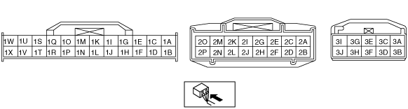
FRONT CLIMATE CONTROL UNIT INSPECTION
id074000805100
1. Connect the front climate control unit connector.
2. Turn the ignition switch to the ON position.
3. Connect the negative (-) lead of the tester to body ground.p
4. By inserting the positive (+) lead of the tester into each front climate control unit terminal, measure the voltage according to the terminal voltage table.
Terminal Voltage Table (Reference)
ac9wzw00001914
|
|
Terminal |
Signal name |
Connected to |
Measurement condition |
Voltage (V) |
Inspection item (s) |
|
|---|---|---|---|---|---|---|
|
1A
|
Motor operation
|
Driver-side front air mix actuator
|
Temperature control dial (driver side): Moving towards COLD
|
1.0 or less
|
• Wiring harness: continuity, short circuit (Front climate control unit—driver-side front air mix actuator: 1A—G, 1D—F)
• Driver-side front air mix actuator
|
|
|
Temperature control dial (driver side): Moving towards HOT
|
B+
|
|||||
|
1B
|
B+
|
ROOM 15 A fuse
|
Under any condition
|
B+
|
• Wiring harness: continuity, short circuit (Front climate control unit— ROOM 15 A fuse)
• ROOM 15 A fuse
|
|
|
1C
|
Motor operation
|
Passenger-side front air mix actuator
|
Temperature control dial (passenger side):
Moving towards COLD*1
Moving towards HOT*2
|
B+
|
• Wiring harness: continuity, short circuit (Front climate control unit—passenger-side front air mix actuator: 1C—G, 1E—F)
• Passenger-side front air mix actuator
|
|
|
Temperature control dial (passenger side):
Moving towards HOT*1
Moving towards COLD*2
|
1.0 or less
|
|||||
|
1D
|
Motor operation
|
Driver-side front air mix actuator
|
Temperature control dial (driver side): Moving towards COLD
|
B+
|
• Wiring harness: continuity, short circuit (Front climate control unit—driver-side front air mix actuator: 1A—G, 1D—F)
• Driver-side front air mix actuator
|
|
|
Temperature control dial (driver-side): Moving towards HOT
|
1.0 or less
|
|||||
|
1E
|
Motor operation
|
Passenger-side front air mix actuator
|
Temperature control dial (passenger side):
Moving towards COLD*1
Moving towards HOT*2
|
1.0 or less
|
• Wiring harness: continuity, short circuit (Front climate control unit—passenger-side front air mix actuator: 1C—G, 1E—F)
• Passenger-side front air mix actuator
|
|
|
Temperature control dial (passenger side):
Moving towards HOT*1
Moving towards COLD*2
|
B+
|
|||||
|
1F
|
Motor operation
|
Front airflow mode actuator
|
Defroster switch on
|
1.0 or less
|
• Wiring harness: continuity, short circuit (Front climate control unit—front airflow mode actuator: 1F—G, 1H—F)
• Front airflow mode actuator
|
|
|
Mode switch: Moving towards VENT
|
B+
|
|||||
|
1G
|
Motor operation
|
Rear air mix actuator
|
Temperature control dial (rear side): Moving towards COLD
|
B+
|
• Wiring harness: continuity, short circuit (Front climate control unit—Rear air mix actuator: 1G—F, 1I—G)
• Rear air mix actuator
|
|
|
Temperature control dial (rear side): Moving towards HOT
|
1.0 or less
|
|||||
|
1H
|
Motor operation
|
Front airflow mode actuator
|
Defroster switch on: Moving towards DEFROSTER
|
B+
|
• Wiring harness: continuity, short circuit (Front climate control unit—front airflow mode actuator: 1F—G, 1H—F)
• Front airflow mode actuator
|
|
|
Mode switch: Moving towards VENT
|
1.0 or less
|
|||||
|
1I
|
Motor operation
|
Rear air mix actuator
|
Temperature control dial (rear side): Moving towards COLD
|
1.0 or less
|
• Wiring harness: continuity, short circuit (Front climate control unit—Rear air mix actuator: 1G—F, 1I—G)
• Rear air mix actuator
|
|
|
Temperature control dial (rear side): Moving towards HOT
|
B+
|
|||||
|
1J
|
Motor operation
|
Rear airflow mode actuator
|
Airflow mode switch (rear side): Moving towards VENT
|
1.0 or less
|
• Wiring harness: continuity, short circuit (Front climate control unit—Rear airflow mode actuator: 1J—G, 1L—F)
• Rear airflow mode actuator
|
|
|
Airflow mode switch (rear side): Moving towards HEAT
|
B+
|
|||||
|
1K
|
Motor operation
|
Air intake actuator
|
REC switch:
Switched to RECIRCULATE*1
Switched to FRESH*2
|
B+
|
• Wiring harness: continuity, short circuit (Front climate control unit—air intake actuator: 1K—A, 1M—C)
• Air intake actuator
|
|
|
REC switch:
Switched to FRESH*1
Switched to RECIRCULATE*2
|
1.0 or less
|
|||||
|
1L
|
Motor operation
|
Rear airflow mode actuator
|
Airflow mode switch (rear side): Moving towards HEAT
|
B+
|
• Wiring harness: continuity, short circuit (Front climate control unit—Rear airflow mode actuator: 1J—G, 1L—F)
• Rear airflow mode actuator
|
|
|
Airflow mode switch (rear side): Moving towards VENT
|
1.0 or less
|
|||||
|
1M
|
Motor operation
|
Air intake actuator
|
REC switch:
Switched to RECIRCULATE*1
Switched to FRESH*2
|
1.0 or less
|
• Wiring harness: continuity, short circuit (Front climate control unit—air intake actuator: 1K—A, 1M—C)
• Air intake actuator
|
|
|
REC switch:
Switched to FRESH*1
Switched to RECIRCULATE*2
|
B+
|
|||||
|
1N
|
Front blower motor feedback
|
Front power MOS FET
|
Airflow volume control dial
|
Off
|
Approx. 7.3
|
1. Wiring harness: continuity, short circuit (Front climate control unit—front power MOS FET: 1N—C, 1P—A)
2. Wiring harness: continuity (Front power MOS FET—body ground: D—ground)
3. Front power MOS FET
4. Front blower motor
5. Front blower relay
6. HEATER 50 A fuse
|
|
1st.
|
Approx. 5.4
|
|||||
|
2nd.
|
Approx. 4.6
|
|||||
|
3rd.
|
Approx. 3.7
|
|||||
|
4th.
|
Approx. 2.9
|
|||||
|
5th.
|
Approx. 2.0
|
|||||
|
6th.
|
Approx. 1.1
|
|||||
|
7th.
|
1.0 or less
|
|||||
|
1O
|
Rear window defroster switch
|
Rear window defroster relay
|
Rear window defroster switch on
|
1.0 or less
|
• Front climate control unit: terminal voltage (1X)
|
|
|
Rear window defroster switch off
|
B+
|
• Wiring harness: open circuit, short circuit (Front climate control unit—rear window defroster relay (main fuse block): 1O—A)
• Rear window defroster relay
|
||||
|
1P
|
Front blower fan speed control
|
Front power MOS FET
|
Airflow volume control dial
|
Off
|
1.0 or less
|
• Front climate control unit: terminal voltage (1N)
|
|
1st.
|
Approx. 2.1
|
|||||
|
2nd.
|
Approx. 2.2
|
|||||
|
3rd.
|
Approx. 2.3
|
|||||
|
4th.
|
Approx. 2.4
|
|||||
|
5th.
|
Approx. 2.5
|
|||||
|
6th.
|
Approx. 2.7
|
|||||
|
7th.
|
Approx. 10.7
|
|||||
|
1Q*5
|
A/C
|
Refrigerant pressure switch
|
Fan switch on, A/C switch on
|
1.0 or less
|
• Front climate control unit: terminal voltage (1W, 1X)
|
|
|
Fan switch off
|
B+
|
• Wiring harness: continuity, short circuit (Front climate control unit—refrigerant pressure switch: 1Q—B) (Refrigerant pressure switch—PCM: C—1B)
• Refrigerant pressure switch
• PCM: terminal voltage (1B)
|
||||
|
1R
|
Rear blower motor feedback
|
Rear power MOS FET
|
Rear airflow volume control dial
|
Off
|
Approx. 8.5
|
1. Wiring harness: continuity, short circuit (Front climate control unit—rear power MOS FET: 1R—D, 1T—C)
2. Wiring harness: continuity (Rear power MOS FET—body ground: A—ground)
3. Rear power MOS FET
4. Rear blower motor
5. Rear blower relay
6. R.HEATER 40 A fuse
|
|
1st.
|
Approx. 6.1
|
|||||
|
2nd.
|
Approx. 4.8
|
|||||
|
3rd.
|
Approx. 3.6
|
|||||
|
4th.
|
Approx. 1.9
|
|||||
|
5th.
|
1.0 or less
|
|||||
|
1S
|
Seat warmer (RH)
|
Seat warmer controller
|
Seat warmer switch off
|
B+
|
• Related wiring harness
• Seat warmer controller
|
|
|
Seat warmer switch 1st
|
Approx. 2.7
|
|||||
|
Seat warmer switch 2nd
|
Approx. 1.7
|
|||||
|
1T
|
Rear blower fan speed control
|
Rear power MOS FET
|
Rear airflow volume control dial
|
Off
|
1.0 or less
|
• Front climate control unit: terminal voltage (1R)
|
|
1st.
|
Approx. 2.1
|
|||||
|
2nd.
|
Approx. 2.2
|
|||||
|
3rd.
|
Approx. 2.2
|
|||||
|
4th.
|
Approx. 2.3
|
|||||
|
5th.
|
Approx. 2.4
|
|||||
|
1U
|
Seat warmer (LH)
|
Seat warmer controller
|
Seat warmer switch off
|
B+
|
• Related wiring harness
• Seat warmer controller
|
|
|
Seat warmer switch 1st
|
Approx. 2.7
|
|||||
|
Seat warmer switch 2nd
|
Approx. 1.7
|
|||||
|
1V*3
|
Seat warmer ground
|
Seat warmer controller
|
Under any condition: Inspect for continuity to ground
|
1.0 or less
|
• Related wiring harness
• Seat warmer controller
|
|
|
1W
|
IG2
|
A/C 7.5 A fuse
|
Ignition switch is at ON position
|
B+
|
• Wiring harness: continuity, short circuit (Front climate control unit— fuse: 1W—A/C 7.5 A)
• A/C 7.5 A fuse
|
|
|
Ignition switch is at LOCK position
|
1.0 or less
|
|||||
|
1X
|
Ground
|
Body ground
|
Under any condition: Inspect for continuity to ground
|
1.0 or less
|
• Wiring harness: continuity (Front climate control unit—ground: 1X—ground)
|
|
|
2A
|
ECT sensor signal
|
Instrument cluster
|
Because this terminal is for communication, good/no good judgment by terminal voltage is not possible.
|
—
|
||
|
2B
|
+5 V
|
• Driver-side front air mix actuator
• Passenger-side front air mix actuator
• Front airflow mode actuator
• Solar radiation sensor
• Rear air mix actuator
• Rear airflow mode actuator
|
Under any condition
|
5.0
|
• Wiring harness: short circuit (Front climate control unit—driver-side front air mix actuator, passenger-side front air mix actuator, front airflow mode actuator, solar radiation sensor, rear air mix actuator, rear airflow mode actuator: 2B—A, A, A, A, A, C)
• Driver-side front air mix actuator
• Passenger-side front air mix actuator
• Front airflow mode actuator
• Solar radiation sensor
• Rear air mix actuator
• Rear airflow mode actuator
|
|
|
2C
|
Information display signal
|
Information display
|
Because this terminal is for communication, good/no good judgment by terminal voltage is not possible.
|
—
|
||
|
2D
|
Potentiometer input
|
Rear airflow mode actuator
|
Airflow mode switch(rear side): Moving towards VENT
|
Approx. 0.5
|
• Wiring harness: continuity, short circuit (Front climate control unit—rear airflow mode actuator: 2D—E)
• Rear airflow mode actuator
• Front climate control unit: terminal voltage (2B)
|
|
|
Airflow mode switch (rear side): Moving towards BI-LEVEL
|
Approx. 2.4
|
|||||
|
Airflow mode switch(rear side): Moving towards HEAT
|
Approx. 4.3
|
|||||
|
2E
|
Potentiometer input
|
Front airflow mode actuator
|
Mode switch: Moving towards VENT
|
Approx. 1.0
|
• Wiring harness: continuity, short circuit (Front climate control unit—front airflow mode actuator: 2E—E)
• Front airflow mode actuator
• Front climate control unit: terminal voltage (2B)
|
|
|
Mode switch: Moving towards BI-LEVEL
|
Approx. 1.9
|
|||||
|
Mode switch: Moving towards HEAT
|
Approx. 2.5
|
|||||
|
Mode switch: Moving towards HEAT/DEF
|
Approx. 3.3
|
|||||
|
Defroster switch on
|
Approx. 4.0
|
|||||
|
2F
|
Potentiometer input
|
Driver-side front air mix actuator
|
Temperature control dial (driver side): Set temperature at MAX COLD
|
4.0
|
• Wiring harness: continuity, short circuit (Front climate control unit—driver-side front air mix actuator: 2F—E)
• Driver-side front air mix actuator
• Front climate control unit: terminal voltage (2B)
|
|
|
Temperature control dial (driver side): Set temperature at MAX HOT
|
1.0
|
|||||
|
2G
|
Potentiometer input
|
Passenger-side front air mix actuator
|
Temperature control dial (passenger side): Set temperature at MAX COLD
|
1.0
|
• Wiring harness: continuity, short circuit (Front climate control unit—passenger-side front air mix actuator: 2G—E)
• Passenger-side front air mix actuator
• Front climate control unit: terminal voltage (2B)
|
|
|
Temperature control dial (passenger side): Set temperature at MAX HOT
|
4.0
|
|||||
|
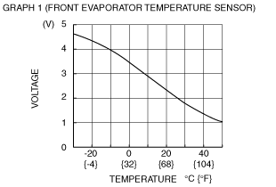
2H
|
Front evaporator temperature sensor input
|
Front evaporator temperature sensor
|
Compared with temperature detected by front evaporator temperature sensor
|
Refer to graph 1
|
• Wiring harness: continuity (Front climate control unit—front evaporator temperature sensor: 2H—B, 2P—A)
• Wiring harness: short circuit (Front climate control unit—front evaporator temperature sensor: 2H—B)
• Front evaporator temperature sensor
|
|
|
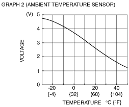
2I
|
Ambient temperature sensor input
|
Ambient temperature sensor
|
Compared with temperature detected by ambient temperature sensor
|
Refer to graph 2
|
• Wiring harness: continuity (Front climate control unit—ambient temperature sensor: 2I—B, 2P—A)
• Wiring harness: short circuit (Front climate control unit—ambient temperature sensor: 2I—B)
• Ambient temperature sensor
|
|
|
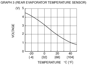
2J
|
Rear evaporator temperature sensor input
|
Rear evaporator temperature sensor
|
Compared with temperature detected by rear evaporator temperature sensor
|
Refer to graph 3
|
• Wiring harness: continuity (Front climate control unit—rear evaporator temperature sensor: 2J—B, 2P—A)
• Wiring harness: short circuit (Front climate control unit—rear evaporator temperature sensor: 2J—B)
• Rear evaporator temperature sensor
|
|
|
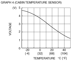
2K
|
Cabin temperature sensor input
|
Cabin temperature sensor
|
Compared with temperature detected by cabin temperature sensor
|
Refer to graph 4
|
• Wiring harness: continuity (Front climate control unit—cabin temperature sensor: 2K—B, 2P—A)
• Wiring harness: short circuit (Front climate control unit—cabin temperature sensor: 2K—B)
• Cabin temperature sensor
|
|
|
2L
|
—
|
—
|
—
|
—
|
—
|
|
|
2M
|
Solar radiation sensor (LH) input
|
Solar radiation sensor
|
Natural sunlight shined directly on the solar radiation sensor
|
4.0
|
• Wiring harness: continuity (Front climate control unit—solar radiation sensor: 2M—C, 2B—A)
• Front climate control unit: terminal voltage (2B)
• Solar radiation sensor
|
|
|
Blocking light to solar radiation sensor
|
1.0 or less
|
|||||
|
2N
|
Potentiometer input
|
Rear air mix actuator
|
Temperature control dial (rear side): Set temperature at MAX COLD
|
1.3
|
• Wiring harness: continuity, short circuit (Front climate control unit—rear air mix actuator: 2N—E)
• Rear air mix actuator
• Front climate control unit: terminal voltage (2B)
|
|
|
Temperature control dial (rear side): Set temperature at MAX HOT
|
4.0
|
|||||
|
2O
|
Solar radiation sensor (RH) input
|
Solar radiation sensor
|
Natural sunlight shined directly on the solar radiation sensor
|
4.0
|
• Wiring harness: continuity (Front climate control unit—solar radiation sensor: 2O—B, 2B—A)
• Front climate control unit: terminal voltage (2B)
• Solar radiation sensor
|
|
|
Blocking light to solar radiation sensor
|
1.0 or less
|
|||||
|
2P
|
Sensor ground
|
• Driver-side front air mix actuator
• Passenger-side front air mix actuator
• Front airflow mode actuator
• Ambient temperature sensor
• Cabin temperature sensor
• Front evaporator temperature sensor
• Rear air mix actuator
• Rear airflow mode actuator
• Rear evaporator temperature sensor
|
Under any condition: Inspect for continuity to ground
|
1.0 or less
|
• Front climate control unit: terminal voltage (1X)
|
|
|
3A
|
—
|
—
|
—
|
—
|
—
|
|
|
3A*4
|
Country destination recognize
|
Body ground
|
Under any condition: Inspect for continuity to ground
|
1.0 or less
|
• Wiring harness: continuity (Front climate control unit—ground: 3A—ground)
|
|
|
3B
|
IG2
|
Rear climate control unit
|
Ignition switch is at ON position
|
B+
|
• Wiring harness: continuity, short circuit (Front climate control unit—rear climate control unit: 3B—B)
• Front climate control unit: terminal voltage (1W, 1X)
|
|
|
Ignition switch is at LOCK position
|
1.0 or less
|
|||||
|
3C
|
Rear climate control unit communication
|
Rear climate control unit
|
Because this terminal is for communication, good/no good judgment by terminal voltage is not possible.
|
—
|
||
|
3D
|
TNS signal
|
ILLUMI 10 A fuse
|
Turn the headlight switch to the off position
|
1.0 or less
|
• Wiring harness: continuity, short circuit (Front climate control unit—ILLUMI 10 A fuse)
• TNS relay
• Headlight switch
|
|
|
Turn the headlight switch to the TNS position
|
B+
|
|||||
|
3E
|
Rear climate control unit communication
|
Rear climate control unit
|
Because this terminal is for communication, good/no good judgment by terminal voltage is not possible.
|
—
|
||
|
3F
|
TNS signal
|
Rear climate control unit
|
Turn the headlight switch to the off position
|
1.0 or less
|
• Wiring harness: continuity, short circuit (Front climate control unit—rear climate control unit: 3F—F)
• ILLUMI 10 A fuse
• TNS relay
• Headlight switch
|
|
|
Turn the headlight switch to the TNS position
|
B+
|
|||||
|
3G
|
On-board diagnostic signal
|
Check connector
|
Check connector is shorted.
|
1.0 or less
|
• Related wiring harness
|
|
|
3H
|
Panel light control
|
Rear climate control unit
|
Turn the headlight switch to the TNS position and panel light control switch at MIN
|
6.76
|
• Wiring harness: continuity, short circuit (Front climate control unit—rear climate control unit: 3H—H)
|
|
|
Turn the headlight switch to the TNS position and panel light control switch at MAX
|
1.0 or less
|
|||||
|
3I
|
Ground
|
Rear climate control unit
|
Under any condition: Inspect for continuity to ground
|
1.0 or less
|
• Wiring harness: continuity (Front climate control unit—rear climate control unit: 3I—I)
|
|
|
3J
|
Panel light control
|
Instrument cluster
|
Turn the headlight switch to the TNS position and panel light control switch at MIN
|
B+
|
• Related wiring harness
• Instrument cluster
|
|
|
Turn the headlight switch to the TNS position and panel light control switch at MAX
|
1.0 or less
|
|||||
|
3K
|
—
|
—
|
—
|
—
|
—
|
|
|
3L
|
—
|
—
|
—
|
—
|
—
|
|
 |
 |
 |
 |