 |
ar8uuw00001876
NAVIGATION CHECK [CAR-NAVIGATION SYSTEM]
id0902f7410400
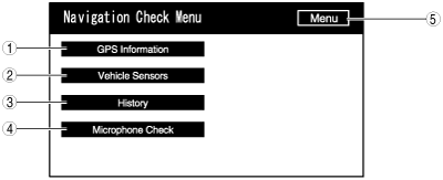
Inspection item list
ar8uuw00001876
|
|
No. |
Name |
Content/function |
|---|---|---|
|
1
|
Display the GPS information.
|
|
|
2
|
Display the vehicle sensors.
|
|
|
3
|
Display the history.
|
|
|
4
|
Verify the microphone condition.
|
|
|
5
|
Menu
|
Return to the Diagnosis Menu.
|
GPS Information
1. Turn ignition switch to ACC or ON position.
2. Launch the diagnostic mode. (See STARTING PROCEDURE FOR DIAGNOSTIC MODE [CAR-NAVIGATION SYSTEM].)
3. Select “Navigation Check”.
4. Select “GPS Information”.
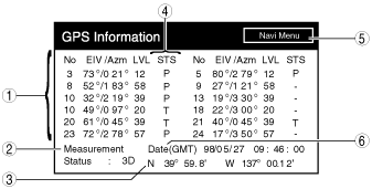
5. Verify the GPS information.
am6zzw00002788
|
|
No. |
Name |
Content/function |
|---|---|---|
|
1
|
Satellite information
|
Display “No (satellite number)”, “elevation angle”, “azimuth”, “signal level” for the satellite.
|
|
2
|
Positioning condition
|
Display any one of the following:
• [2D]: During two-dimensional positioning
• [3D]: During three-dimensional positioning
• [NG]: When positioning data is unavailable
• [error]: During reception error occurrence
• [—]: Other than the above
|
|
3
|
Position
|
Display the latitude and longitude of the current position.
|
|
4
|
GPS reception condition
|
Display any one of the following:
• [P]: If the applicable satellite is being used in the vehicle’s current position.
• [T]: If receiving but not being used in the vehicle’s current position
• [—]: If reception is not possible from applicable satellite
|
|
5
|
Navi Menu
|
Return to the Navigation Check Menu.
|
|
6
|
Day and time
|
Display the day/time information
|
6. To stop the on-board diagnostic mode, turn the ignition switch to the LOCK position.
Vehicle Sensors
1. Turn ignition switch to ACC or ON position.
2. Launch the diagnostic mode. (See STARTING PROCEDURE FOR DIAGNOSTIC MODE [CAR-NAVIGATION SYSTEM].)
3. Select “Navigation Check”.
4. Select “Vehicle Sensors”.
5. Verify the sensor output condition of the sensor being input to the car-navigation unit.
ac9uuw00002990
|
|
No. |
Name |
Content/function |
|---|---|---|
|
1
|
Navi Menu
|
Return to the Navigation Check Menu.
|
|
2
|
Gyro Voltage
|
Display the gyro sensor voltage
|
|
3
|
Relative bearing
|
Display the gyro sensor relative bearing
|
|
4
|
Reset
|
Reset the following display items, and the display content to 0.
• Gyro sensor voltage
• Gyro sensor relative bearing
|
6. To stop the on-board diagnostic mode, turn the ignition switch to the LOCK position.
History
1. Turn ignition switch to ACC or ON position.
2. Launch the diagnostic mode. (See STARTING PROCEDURE FOR DIAGNOSTIC MODE [CAR-NAVIGATION SYSTEM].)
3. Select “Navigation Check”.
4. Select “History”.
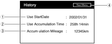
5. Verify the displayed content.
am6zzw00002270
|
|
No. |
Name |
Content/function |
|---|---|---|
|
1
|
Use Start Date
|
Display the date for the start of use.
|
|
2
|
Use Accumulation Time
|
Display the accumulated use time.
|
|
3
|
Accumulation Mileage
|
Display the accumulated travel distance.
|
|
4
|
Navi Menu
|
Return to the Navigation Check Menu.
|
6. To stop the on-board diagnostic mode, turn the ignition switch to the LOCK position.
Microphone Check
1. Turn ignition switch to ACC or ON position.
2. Launch the diagnostic mode. (See STARTING PROCEDURE FOR DIAGNOSTIC MODE [CAR-NAVIGATION SYSTEM].)
3. Select “Navigation Check”.
4. Select “Microphone Check”.
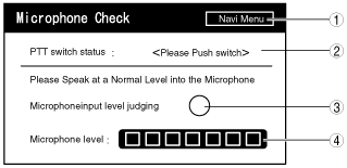
5. Verify the microphone input condition.
ac9uuw00002991
|
|
No. |
Name |
Content/function |
|---|---|---|
|
1
|
Navi Menu
|
Return to the Navigation Check Menu.
|
|
2
|
Talk switch status
|
Display the talk switch condition.
|
|
3
|
Microphone inspection results indicator
|
Display the microphone inspection results
|
|
4
|
Microphone input level gauge
|
Display the volume at 8 levels.
|
6. To stop the on-board diagnostic mode, turn the ignition switch to the LOCK position.