|
1
|
INSPECT THEFT-DETERRENT SIREN CONNECTOR
• Turn the ignition switch to the LOCK position.
• Disconnect the negative battery cable.
• Disconnect the theft-deterrent siren connector.
• Inspect the theft-deterrent siren connector.(Corrosion, damage, and disconnected pins)
• Is there any malfunction?
|
Yes
|
Repair or replace the connector or terminals, then go to Step 7.
|
|
No
|
Go to the next step.
|
|
2
|
INSPECT THEFT-DETERRENT CONTROL MODULE CONNECTOR
• Disconnect the theft-deterrent control module connector.
• Inspect the theft-deterrent control module connector. (Corrosion, damage, and disconnected pins)
• Is there any malfunction?
|
Yes
|
Repair or replace the connector or terminals, then go to Step 7.
|
|
No
|
Go to the next step.
|
|
3
|
INSPECT THEFT-DETERRENT SIREN SIGNAL CIRCUIT FOR SHORT TO GROUND
• Verify that the theft-deterrent siren and theft-deterrent control module connectors are disconnected.
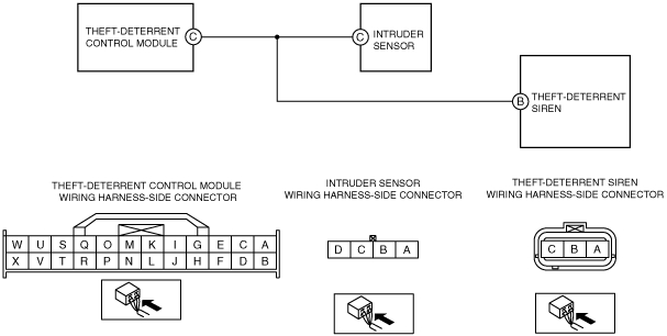
• Inspect for continuity between theft-deterrent siren terminal B (wiring harness-side) and body ground.
• Is there continuity?
|
Yes
|
Repair or replace the wiring harness for a possible short to ground, then go to Step 7.
|
|
No
|
Go to the next step.
|
|
4
|
INSPECT THEFT-DETERRENT SIREN SIGNAL CIRCUIT FOR SHORT TO POWER SUPPLY
• Verify that the theft-deterrent siren and theft-deterrent control module connectors are disconnected.
• Reconnect the negative battery cable.
• Turn the ignition switch to the ON position.
• Measure the voltage at the theft-deterrent siren terminal B (wiring harness-side).
• Is there any voltage?
|
Yes
|
Repair or replace the wiring harness for a possible short to power supply, then go to Step 7.
|
|
No
|
Go to the next step.
|
|
5
|
INSPECT THEFT-DETERRENT SIREN SIGNAL CIRCUIT FOR OPEN CIRCUIT
• Verify that the theft-deterrent siren and theft-deterrent control module connectors are disconnected.
• Turn the ignition switch to the LOCK position.
• Disconnect the negative battery cable.
• Inspect for continuity between theft-deterrent siren terminal B (wiring harness-side) and theft-deterrent control module terminal C (wiring harness-side).
• Is there continuity?
|
Yes
|
Go to the next step.
|
|
No
|
Repair or replace the wiring harness for a possible open circuit, then go to Step 7.
|
|
6
|
INSPECT THEFT-DETERRENT SIREN
• Inspect the theft-deterrent siren.
• Is there any malfunction?
|
Yes
|
Replace the theft-deterrent siren, then go to the next step.
|
|
No
|
Go to the next step.
|
|
7
|
VERIFY TROUBLESHOOTING COMPLETED
• Make sure to reconnect all disconnected connectors.
• Reconnect the negative battery cable.
• Clear DTCs using the M-MDS.
• Perform the theft-deterrent control module DTC inspection using the M-MDS.
• Is the same DTC present?
|
Yes
|
Repeat the inspection from Step 1.
• If the malfunction recurs, replace the theft-deterrent control module.
Go to the next step.
|
|
No
|
Go to the next step.
|
|
8
|
VERIFY THAT NO OTHER DTCs ARE PRESENT
• Are any DTCs present?
|
Yes
|
Go to the applicable DTC inspection.
|
|
No
|
DTC troubleshooting completed.
|